Chapter 1 NIC interface naming convention
In order to facilitate finding and distinguishing network interfaces and ensure the consistency and visibility of network interfaces, OpenCloudOS provides a naming convention for network interfaces.
Network interface names consist of a fixed prefix and a serial number generated by the kernel to initialize the network device. For example, eth0 represents the first network device detected by the system at boot time, but these names do not necessarily correspond to the label names on the host's shell. Ambiguous interface naming may be encountered on servers with multiple network adapters, which affects embedded network adapters and additional adapters in the system.
In OpenCloudOS, the udev device manager supports various naming schemes. By default, udev assigns names to devices based on firmware, topology and location information, which has several advantages:
- Device names are fully predictable.
- Adding or removing hardware will not change the device name as the serial number will not be regenerated.
- Facilitates replacement of faulty hardware.
1.1 Network interface device naming scheme
Following is the udev device manager default device naming scheme:
| Scenario | Description | Example |
|---|---|---|
| 1 | The device name contains the BIOS index number or firmware, applicable to the device on the motherboard. When this scheme is not applicable, udev will use scheme 2. | eno1 |
| 2 | The device name contains the PCIe hot-plug slot index number provided by the firmware or BIOS. When this scheme is not applicable, udev will use scheme 3. | ens1 |
| 3 | The device name contains the physical location of the hardware connector. When this scheme is not applicable, udev will use scheme 5. | enp2s0 |
| 4 | The device name contains the MAC address. OpenCloudOS does not use this scheme by default, but administrators can choose to use it. | enx00ff2420b540 |
| 5 | Legacy unforeseen kernel naming schemes. The device manager uses this scheme if udev cannot apply any other scheme. | eth0 |
By default, OpenCloudOS chooses the device name according to the NamePolicy setting in the /usr/lib/systemd/network/99-default.link file. The order of the values in the NamePolicy is important. OpenCloudOS uses the first device name specified in the file and generated by udev.
If you manually configure udev rules to change kernel device names, those rules take precedence.
1.2. Working method of network device renaming
By default, OpenCloudOS enables the same device naming rules. The udev device manager renames devices according to different schemes. The following list describes the order in which udev handles these scenarios, and the actions these rules are responsible for:
- The /usr/lib/udev/rules.d/60-net.rules file defines the /lib/udev/rename_device helper tool to search the /etc/sysconfig/network-scripts/ifcfg-* files for the HWADDR parameter. When the NIC MAC address matches the value set by the variable, the helper tool renames the NIC interface to the name in the DEVICE parameter of the file.
- The /usr/lib/udev/rules.d/71-biosdevname.rules file defines the biosdevname tool to rename the interface according to its naming policy if the device was not renamed in the previous step.
- The /usr/lib/udev/rules.d/75-net-description.rules file defines what udev checks for network interface devices and sets properties in the udev-internal variable that will be processed in the next step. Note that some of these properties may not be defined.
- The /usr/lib/udev/rules.d/80-net-setup-link.rules file calls the built-in net_setup_link udev and then applies the renaming scheme. The following are the default policies stored in the /usr/lib/systemd/network/99-default.link file:
[Link]
NamePolicy=kernel database onboard slot path
MACAddressPolicy=persistent
With this policy, udev will not rename interfaces if the kernel uses persistent names. If the kernel does not use persistent names, udev will rename the interface to the name provided by udev's hardware database. If this database is not available, OpenCloudOS falls back to the above mechanism.
Also, for interface names based on Media Access Control (MAC) addresses, set the NamePolicy parameter in this file to mac. 5. The /usr/lib/udev/rules.d/80-net-setup-link.rules file defines that udev renames interfaces according to the udev-internal parameter in the following order:
- ID_NET_NAME_ONBOARD
- ID_NET_NAME_SLOT
- ID_NET_NAME_PATH If no parameter is set, udev will use the next parameter. If no parameters are set, the interface will not be renamed.
Steps 3 and 4 implement the naming schemes 1 through 4 described in Network Interface Device Naming Scheme.
Predictable network interface name interpretation on 1.3.x86_64 platforms
When the consistent network device names feature is enabled, the udev device manager creates device names according to different standards. This section explains the naming scheme when installing OpenCloudOS on x86_64 platforms.
Interface names begin with a two-character prefix based on the interface type:
- en for Ethernet
- wl for wireless LAN (WLAN)
- ww for Wireless Wide Area Network (WWAN)
Additionally, one of the following is appended to one of the above prefixes depending on the mode applied by the udev device manager:
- o
- s
[f\ ][d]
Note that all multifunction PCI devices contain the number [f\
The [P\
For USB devices, the full chain of hub port numbers consists of the hub's port numbers. If the name is larger than the maximum (15 characters), it will not be exported. If there are multiple USB devices in the chain, udev suppresses the default values for the USB configuration descriptor (c1) and USB interface descriptor (i0).
1.4. Predictable Network Interface Device Name Interpretation in System z Platforms
The udev device manager on System z platforms creates device names based on bus IDs when the consistent network device names feature is enabled. The bus ID identifies a device in the s390 channel subsystem.
For channel command word (CCW) devices, the bus ID is the device number prefixed with 0.n, where n is the subchannel set ID.
For example, an Ethernet interface is named enccw0.0.1234. For example, a Serial Line Internet Protocol (SLIP) channel-to-channel (CTC) network device is named slccw0.0.1234.
Use the znetconf -c or lscss -a commands to display available network devices and their bus IDs.
1.5. Disable interface device naming conventions during installation
This section describes how to disable interface device naming conventions during installation.
OpenCloudOS recommends against disabling this specification. Disabling the interface device naming convention may cause different types of problems, for example, after adding a network card, the device name assigned by the kernel will not be fixed, and the kernel may use different schemes to name the network card after each reboot.
process:
- Boot the OpenCloudOS installation media
- In Boot Manager, select Install OpenCloudOS and press the [Tab] key to edit the entry.
- Append the net.ifnames=0 parameter to the kernel command line:
vmlinu... net.ifnames=0
1.6. Disable interface device naming conventions in installed systems
This section describes how to disable interface device naming conventions on an installed Open Cloud OS system.
OpenCloudOS recommends against disabling this specification. Disabling the interface device naming convention may cause different types of problems, for example, after adding a network card, the device name assigned by the kernel will not be fixed, and the kernel may use different schemes to name the network card after each reboot.
Prerequisites
- The system has used the interface device naming convention by default
process
- Edit the /etc/default/grub file and append the net.ifnames=0 parameter to the GRUB_CMDLINE_LINUX variable:
GRUB_CMDLINE_LINUX="...net.ifnames=0"
-
On systems with UEFI boot mode:
- On systems using the old boot mode:# grub2-mkconfig -o /boot/efi/EFI/redhat/grub.cfg3. Display the current profile name and associated device name:# grub2-mkconfig -o /boot/grub2/grub.cfg
# nmcli -f NAME,DEVICE,FILENAME connection show
 NAME           DEVICE  FILENAME
 System enp1s0  enp1s0  /etc/sysconfig/network-scripts/ifcfg-enp1s0
 System enp7s0  enp7s0  /etc/NetworkManager/system-connections/enp7s0.nmconnection
Note which profile and file name each device is associated with. 4. Remove the HWADDR parameter from all connection profiles:
# sed -i '/^HWADDR=/d' /etc/sysconfig/network-scripts/ifcfg-enp1s0 /etc/NetworkManager/system-connections/enp7s0.nmconnection
# ip link show
...
2: enp1s0: <BROADCAST,MULTICAST,UP,LOWER_UP> mtu 1500 qdisc fq_codel state UP mode DEFAULT group default qlen 1000
     link/ether 00:53:00:c5:98:1c brd ff:ff:ff:ff:ff:ff
3: enp7s0: <BROADCAST,MULTICAST,UP,LOWER_UP> mtu 1500 qdisc fq_codel state UP mode DEFAULT group default qlen 1000
     link/ether 00:53:00:b6:87:c6 brd ff:ff:ff:ff:ff:ff
# reboot
# ip link show
 ...
 2: eth0: <BROADCAST,MULTICAST,UP,LOWER_UP> mtu 1500 qdisc fq_codel state UP mode DEFAULT group default qlen 1000
     link/ether 00:53:00:b6:87:c6 brd ff:ff:ff:ff:ff:ff
 3: eth1: <BROADCAST,MULTICAST,UP,LOWER_UP> mtu 1500 qdisc fq_codel state UP mode DEFAULT group default qlen 1000
     link/ether 00:53:00:c5:98:1c brd ff:ff:ff:ff:ff:ff
If you compare the current output with the previous output:
- Interface enp7s0 (MAC address 00:53:00:b6:87:c6 ) is named eth0 now.
- Interface enp1s0 (MAC address 00:53:00:c5:98:1c ) is named eth1 now.
- Rename the configuration file:
# mv /etc/NetworkManager/system-connections/enp7s0.nmconnection /etc/NetworkManager/system-connections/eth0.nmconnection
# mv /etc/sysconfig/network-scripts/ifcfg-enp1s0 /etc/sysconfig/network-scripts/ifcfg-eth1
# nmcli connetction reload
```
# nmcli -f NAME,DEVICE,FILENAME connection show
NAME           FILENAME
System enp7s0  /etc/NetworkManager/system-connections/eth0.nmconnection
System enp1s0  /etc/sysconfig/network-scripts/ifcfg-eth1
```

Configure the file name in the next step.
-
Rename the NetworkManager connection profiles and update the interface names in each profile:
12. Reactivate the NetworkManager connection:# nmcli connection modify "System enp7s0" connection.id eth0 connection.interface-name eth0 # nmcli connection modify "System enp1s0" connection.id eth1 connection.interface-name eth1# nmcli connection up eth0 # nmcli connection up eth1
1.7. Custom Ethernet interface prefix
This section describes how to customize the prefix of Ethernet interface names during Open Cloud OS installation.
Customizing prefixes using the prefixdevname tool on installed systems is not currently supported.
After Open Cloud OS installation, the udev service will name ethernet devices in the format \
Prerequisites
- The prefix format requirements to be set are as follows:
- consists of ASCII characters
- only letters and numbers
- less than 16 characters
- Does not conflict with any existing network interface prefixes such as eth , eno , ens and em .
process
- Boot the Open Cloud OS installation media.
- In Boot Manager: a.
- Select the Install Open CLoud OS\
option and press the [Tab] key to edit the option. - Append net.ifnames.prefix=\
to the kernel options. - Press the [Enter] key to start the installer.
- Install Open Cloud OS.
verify
- After installation, show ethernet interface:
# ip link show
  ...
  2: net0: <BROADCAST,MULTICAST,UP,LOWER_UP> mtu 1500 qdisc fq_codel state UP mode DEFAULT group default qlen 1000
      link/ether 00:53:00:c5:98:1c brd ff:ff:ff:ff:ff:ff
  3: net1: <BROADCAST,MULTICAST,UP,LOWER_UP> mtu 1500 qdisc fq_codel state UP mode DEFAULT group default qlen 1000
      link/ether 00:53:00:c2:39:9e brd ff:ff:ff:ff:ff:ff
  ...
1.8. Assign custom network interface names using udev device manager
udev device manager supports a set of rules to customize interface names
process
- Display all network interfaces and their MAC addresses:
# ip link list

 enp6s0f0: <BROADCAST,MULTICAST,UP,LOWER_UP> mtu 1500 qdisc fq_codel state UP mode DEFAULT group default qlen 1000
     link/ether b4:96:91:14:ae:58 brd ff:ff:ff:ff:ff:ff
 enp6s0f1: <BROADCAST,MULTICAST,UP,LOWER_UP> mtu 1500 qdisc fq_codel state UP mode DEFAULT group default qlen 1000
     link/ether b4:96:91:14:ae:5a brd ff:ff:ff:ff:ff:ff
 enp4s0f0: <BROADCAST,MULTICAST,UP,LOWER_UP> mtu 1500 qdisc fq_codel state UP mode DEFAULT group default qlen 1000
     link/ether 00:90:fa:6a:7d:90 brd ff:ff:ff:ff:ff:ff
SUBSYSTEM=="net",ACTION=="add",ATTR{address}=="b4:96:91:14:ae:58",ATTR{type}=="1",NAME="provider0"
SUBSYSTEM=="net",ACTION=="add",ATTR{address}=="b4:96:91:14:ae:5a",ATTR{type}=="1",NAME="provider1"
SUBSYSTEM=="net",ACTION=="add",ATTR{address}=="00:90:fa:6a:7d:90",ATTR{type}=="1",NAME="provider2"
These rules match the MAC addresses of network interfaces and rename them to the names specified in the NAME property. In these examples, the ATTR{type} parameter value set to 1 defines the interface type as Ethernet .
verify
- Restart the system:
# reboot
# ip link show

provider0: <BROADCAST,MULTICAST,UP,LOWER_UP> mtu 1500 qdisc mq state UP mode DEFAULT group default qlen 1000
    link/ether b4:96:91:14:ae:58 brd ff:ff:ff:ff:ff:ff
altname enp6s0f0
provider1: <BROADCAST,MULTICAST,UP,LOWER_UP> mtu 1500 qdisc mq state UP mode DEFAULT group default qlen 1000
    link/ether b4:96:91:14:ae:5a brd ff:ff:ff:ff:ff:ff
    altname enp6s0f1
provider2: <BROADCAST,MULTICAST,UP,LOWER_UP> mtu 1500 qdisc mq state UP mode DEFAULT group default qlen 1000
    link/ether 00:90:fa:6a:7d:90 brd ff:ff:ff:ff:ff:ff
    altname enp4s0f0
1.9. Assign user-defined network interface names using the systemd linker file
Create a naming scheme by renaming the network interface to provider0.
process
- Display all interface names and their MAC addresses:
# ip link show

enp6s0f0: <BROADCAST,MULTICAST,UP,LOWER_UP> mtu 1500 qdisc fq_codel state UP mode DEFAULT group default qlen 1000
    link/ether b4:96:91:14:ae:58 brd ff:ff:ff:ff:ff:ff
enp6s0f1: <BROADCAST,MULTICAST,UP,LOWER_UP> mtu 1500 qdisc fq_codel state UP mode DEFAULT group default qlen 1000
    link/ether b4:96:91:14:ae:5a brd ff:ff:ff:ff:ff:ff
enp4s0f0: <BROADCAST,MULTICAST,UP,LOWER_UP> mtu 1500 qdisc fq_codel state UP mode DEFAULT group default qlen 1000
    link/ether 00:90:fa:6a:7d:90 brd ff:ff:ff:ff:ff:ff
[Match]
MACAddress=b4:96:91:14:ae:58

[Link]
Name=provider0
This link file matches the MAC address and renames the network interface to the name set in the Name parameter.
verify
- Restart the system:
# reboot
# ip link show

provider0: <BROADCAST,MULTICAST,UP,LOWER_UP> mtu 1500 qdisc mq state UP mode DEFAULT group default qlen 1000
    link/ether b4:96:91:14:ae:58 brd ff:ff:ff:ff:ff:ff
Chapter 2 Getting Started with NetworkManager
By default, Open Cloud OS uses NetworkManager to manage and configure network connections.
2.1. Advantages of NetworkManager
The main advantages of using NetworkManager are:
- Provides an API via D-Bus, which allows querying and controlling network configuration and status. This allows multiple applications to check and configure the network, ensuring a synchronized and up-to-date network state. For example, the web console (monitoring and configuration services via a web browser) uses the NetworkManager D-BUS interface to configure the network, and the Gnome GUI, nmcli, and nm-connection-editor tools. Every change made to these tools will be detected by all other users.
- More convenient mirroring of network configuration: NetworkManager (NetworkManager) ensures that network connections are working properly. NetworkManager creates temporary connections to provide connectivity when it finds that there is no network configuration but there are network devices in the system.
- Provides users with easy connection setup: NetworkManager provides management through different tools - GUI, nmtui, nmcli.
- Support flexible configuration. For example, configure a WiFi interface and NetworkManager will scan and display available wifi networks. You can select an interface and NetworkManager will display the credentials needed to provide an automatic connection after the restart process. NetworkManager can configure network aliases, IP addresses, static routes, DNS information, and VPN connections as well as many connection-specific parameters. You can modify the configuration options to suit your needs.
- Persist the device state after the restart process and take over the interface that was set to managed mode during the restart process.
- Handles devices that are not explicitly set but are manually controlled by a user or other network device.
2.2. Overview of tools and programs for NetworkManager management connections
You can try the following tools to manage NetworkManager connections:
- nmcli : A command-line tool for managing connections.
- nmtui : Mouse cursor based to Text User Interface (TUI). Requires the NetworkManager-tui package to be installed.
- nm-connection-editor : Graphical User Interface (GUI) for NetworkManager related tasks. To start the program, type nm-connection-editor in a GNOME session terminal.
- control-center : GNOME Shell's GUI for desktop users. Note that this program supports fewer features than nm-connection-editor.
- Network Connection Icon in GNOME Shell: This icon indicates the status of your network connection and acts as a visual indicator of the type of connection you are using.
2.3. Load the manually configured ifcfg file into NetworkManager
In Open Cloud OS, if you edit the ifcfg file, NetworkManager does not automatically pick up the change. If you use one of these tools to update NetworkManager profile settings, NetworkManager will not implement those changes until you reconnect using that profile. For example, if a configuration file is modified using an editor, NetworkManager must read the configuration file again.
NetworkManager supports configuration sets stored in keyfile format. However, NetworkManager uses the ifcfg format by default when creating or updating configuration files using the NetworkManager API.
The /etc/sysconfig/ directory is where configuration files and scripts are located. With the exception of VPN, Mobile Broadband, and PPPoE configuration, most network configuration information is stored in the /etc/NetworkManager/ subdirectory. For example, interface-specific information is stored in the ifcfg file in the /etc/sysconfig/network-scripts/ directory.
Information for VPN, Mobile Broadband and PPPoE connections is stored in /etc/NetworkManager/system-connections/.
process
- To load a new configuration file:
# nmcli connection load /etc/sysconfig/network-scripts/ifcfg-connection_name
# nmcli connection up connection_name
Chapter 3 Configuring NetworkManager to ignore certain devices
By default, NetworkManager manages all devices except the lo (loopback) device. However, you can configure NetworkManager to ignore certain devices, making them unmanaged. With this setting, you can manage these devices manually, for example using scripts.
3.1. Configure permanent unmanaged devices
You can configure a device to be unmanaged based on several criteria, such as interface name, MAC address, or device type. The following procedure describes how to permanently set the enp1s0 interface to unmanaged in NetworkManager.
process
- Optional: Display a list of devices to identify the device you want to set as unmanaged:
# nmcli device status
DEVICE  TYPE      STATE         CONNECTION
enp1s0  ethernet  disconnected  --
...
[keyfile]
unmanaged-devices=interface-name:enp1s0
To set multiple devices as unmanaged, separate the entries in the unmanaged-devices parameter with semicolons:
[keyfile]
unmanaged-devices=interface-name:interface_1;interface-name:interface_2;...
# systemctl reload NetworkManager
verify
- Display device list:
# nmcli device status
DEVICE  TYPE      STATE      CONNECTION
enp1s0  ethernet  unmanaged  --
...
The unmanaged status next to the enp1s0 device indicates that NetworkManager is not managing the device.
3.2. Configure temporary unmanaged devices
You can configure a device to be unmanaged based on several criteria, such as interface name, MAC address, or device type. This procedure describes how to temporarily set the enp1s0 interface to unmanaged in NetworkManager.
process
- Optional: Display a list of devices to identify the device you want to set as unmanaged:
# nmcli device status
DEVICE  TYPE      STATE         CONNECTION
enp1s0  ethernet  disconnected  --
...
# nmcli device set enp1s0 managed no
verify
- Display device list:
# nmcli device status
DEVICE  TYPE      STATE      CONNECTION
enp1s0  ethernet  unmanaged  --
...
The unmanaged status next to the enp1s0 device indicates that NetworkManager is not managing the device.
Chapter 4 Using the nmtui Text Interface to Manage Network Connections
4.1. Start the nmtui tool
Prerequisites
- NetworkManager-tui package installed
process
- Start nmtui and enter at the command line:
# nmtui
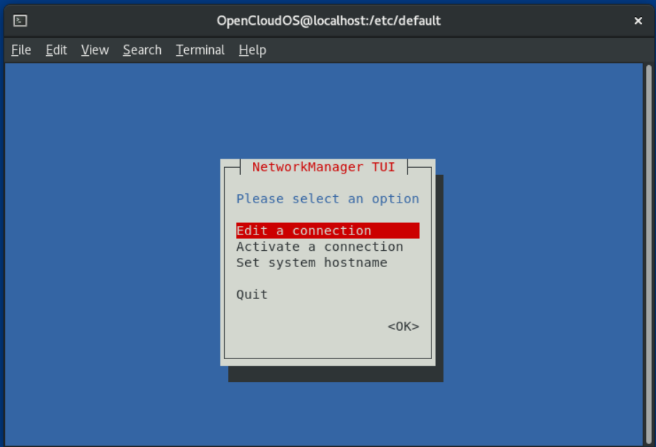 2. Enter nmtui:
- In options, use the cursor or press the [Tab] key to move forward, press [Shift]+[Tab] to go back.
- Use [Enter] to select an option.
- Use [Space] to toggle the checkbox state.
4.2. Use nmtui to add connection configuration set
Prerequisites
- NetworkManager-tui package installed
process
- Start nmtui and enter at the command line:
# nmtui
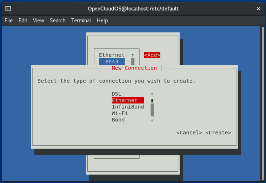 5. Enter the connection details.
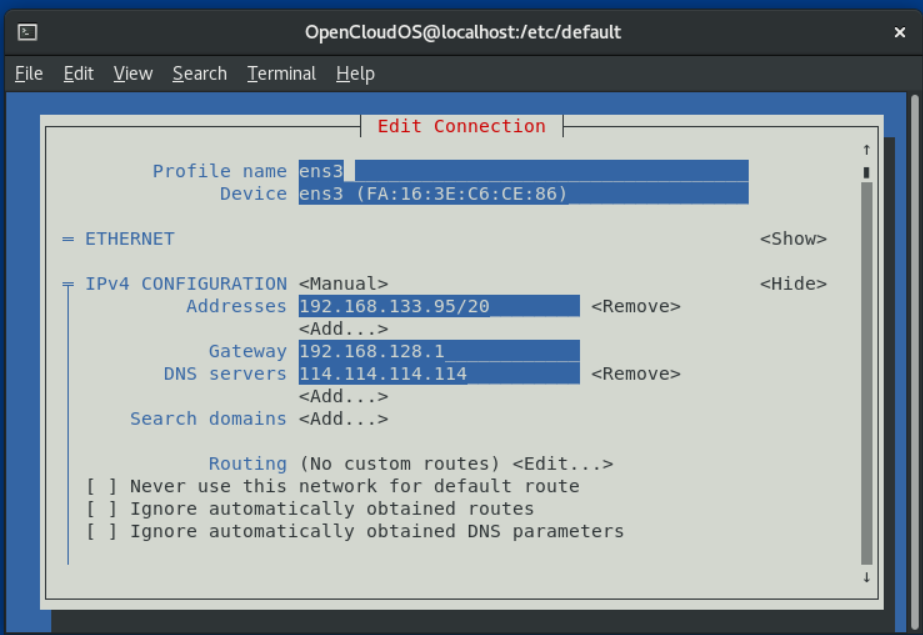 6. Select [OK] to save the changes.
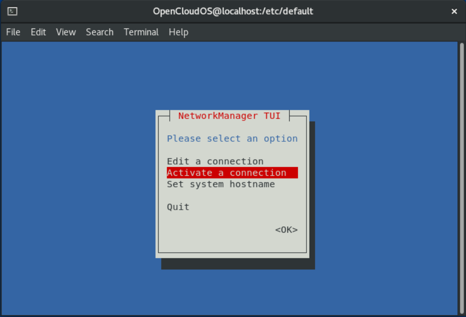
7. Select Back to return to the main menu.
8. Select Activate a connection and select [Enter].
9. Select the new connection and press [Enter] to activate the connection.
10. Select [Back] to return to the main menu.
11. Choose Quit.
6. Select [OK] to save the changes.
7. Select Back to return to the main menu.
8. Select Activate a connection and select [Enter].
9. Select the new connection and press [Enter] to activate the connection.
10. Select [Back] to return to the main menu.
11. Choose Quit.
verify
- Display device and connection status:
# nmcli device status
DEVICE      TYPE      STATE      CONNECTION
ens3      ethernet  connected  ens3
# nmcli connection show ens3
connection.id:                          ens3
connection.uuid:                        f46c8406-74f4-458f-a884-a1889377aebc
connection.stable-id:                   --
connection.type:                        802-3-ethernet
connection.interface-name:              ens3
connection.autoconnect:                 yes
connection.autoconnect-priority:        0
...
Note that if the configuration on disk does not match the configuration in the device, starting or restarting NetworkManager will create an in-memory connection representing the device's configuration.
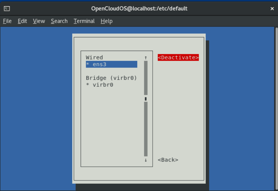
4.3. Change connection using nmtui application
After modifying a connection in nmtui, you must reactivate the connection. Note that reactivating a connection in nmtui temporarily deactivates the connection.
Prerequisites
- The connection profile does not have the auto-connect setting enabled.
process
- Select the Activate a connection option from the main menu:
- Select the modified connection.
- On the right, select the Deactivate button and press [Enter]:
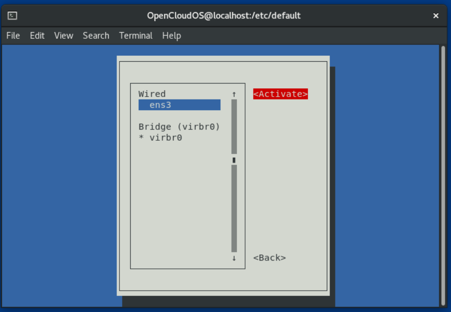
- Select Connect again.
- On the right, select the Activate button and press [Enter]:
Chapter 5 Getting Started with nmcli
5.1. nmcli output in different formats
The nmcli tool supports controlling the output of commands through different parameters. By using these options, you can display only the information you need. This simplifies the process of processing output in scripts.
By default, nmcli displays its output in a table-like format:
# nmcli device
DEVICE      TYPE      STATE                   CONNECTION
ens3        ethernet  connected               ens3
virbr0      bridge    connected (externally)  virbr0
lo          loopback  unmanaged               --
virbr0-nic  tun       unmanaged               --
Using the -f parameter, you can display columns in a custom order, for example:
# nmcli -f DEVICE,STATE device
DEVICE      STATE
ens3        connected
virbr0      connected (externally)
lo          unmanaged
virbr0-nic  unmanaged
Use the -t parameter to display each field of the output in colon-separated form:
# nmcli -t device
ens3:ethernet:connected:ens3
virbr0:bridge:connected (externally):virbr0
lo:loopback:unmanaged:
virbr0-nic:tun:unmanaged:
When you use a script to process output, combine -f with -t to display only specific fields in colon-separated form:
# nmcli -f DEVICE,STATE -t device
ens3:connected
virbr0:connected (externally)
lo:unmanaged
virbr0-nic:unmanaged
5.2. Use the tab key to automatically complete nmcli commands
The nmcli tool supports tab completion if the bash-completion package is installed on your host machine. This allows you to autocomplete option names and identify possible options and values.
For example, if you type nmcli con and press Tab, the shell autocompletes the command nmcli connection.
The option or value you enter must be unique. If it is not unique, nmcli displays all possible options. For example, if you type nmcli connection d , and press Tab , the command displays the commands delete and down as possible options.
You can also use tab completion to display all properties that can be set in a connection configuration set. For example, if you type nmcli connection modify connection_name and press Tab, the command displays the full list of available properties.
5.3. Commonly used nmcli commands
- Display a list of connection profiles:
# nmcli connection show
NAME    UUID                                  TYPE      DEVICE
ens3    f46c8406-74f4-458f-a884-a1889377aebc  ethernet  ens3
# nmcli connection show CONNECTION-NAME
connection.id:                          ens3
connection.uuid:                        f46c8406-74f4-458f-a884-a1889377aebc
connection.stable-id:                   --
connection.type:                        802-3-ethernet
connection.interface-name:              ens3
connection.autoconnect:                 yes
...
nmcli connection modify CONNECTION-NAME PROPERTY VALUE
Supports simultaneous modification of multiple properties using multiple PROPERTY VALUE combinations. - Displays a list of network devices, status, type and connection sets:
# nmcli device
DEVICE      TYPE      STATE                   CONNECTION
ens3        ethernet  connected               ens3
...
# nmcli connection up CONNECTION-NAME
# nmcli connection down CONNECTION-NAME
Chapter 6 Getting started with configuring a network using the GNOME GUI
You can manage and configure network connections in GNOME using:
- the GNOME Shell network connection icon in the upper right corner of the desktop
- GNOME control-center application
- GNOME nm-connection-editor application
6.1. Manage network connections through desktop icons
Prerequisites
- The GNOME package group is installed.
- You are logged into GNOME.
- If the network requires specific configuration, such as a static IP address or 802.1x configuration, then a connection profile needs to have been created.
process
- Click the network connection icon in the upper right corner of the desktop.
 2. Depending on the connection type, select Wired or Wi-Fi.
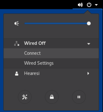 3. For a wired connection, select Connect to connect to the network.
4. For a Wi-Fi connection, tap Select network, choose the network you want to connect to, and enter the password
3. For a wired connection, select Connect to connect to the network.
4. For a Wi-Fi connection, tap Select network, choose the network you want to connect to, and enter the password
Chapter 7 Introduction to Nmstate
Nmstate is a declarative network management tool. The nmstate software provides the libnmstate Python library, and nmstatectl, a command-line tool for managing NetworkManager. When using Nmstate, you can describe the expected network state using descriptions in YAML or JSON format.
Advantages of using Nmstate:
- Provides a stable and extensible interface to manage OpenCLoudOS network functions
- Supports atomic and transactional operations at the host and cluster levels
- Supports partial editing of most properties and preserves existing settings not specified in description
- Provides plugin support to enable administrators to use their own plugins
7.1. Using libnmstate library in Python program
The libnmstate Python library enables developers to use Nmstate in their own applications
To use the library, import it in your source code:
import libnmstate
Note that you must have the nmstate package installed to use this library.
Case: Use the libnmstate library to query the network status
The following code imports the libnmstate library and displays the available network interfaces and their states:
import json
import libnmstate
from libnmstate.schema import Interface


net_state = libnmstate. show()
for iface_state in net_state[Interface.KEY]:
print(iface_state[Interface.NAME] + ": "
    + iface_state[Interface.STATE])
7.2. Use nmstatectl to update the network configuration
You can use the nmstatectl tool to store the current network configuration for one or more interfaces in a file. Then you can use this file:
- Modify the configuration and apply it to the same system.
- Copy the files to other hosts and configure the hosts with the same or modified settings.
Here's how to export the settings for the ens3 interface to a file, modify the configuration, and apply the settings on the host.
Prerequisites
- The nmstate package is installed.
process
- Export the settings of the ens3 interface to the ~/network-config.yml file:
# nmstatectl show ens3 > ~/network-config.yml
This command will store ens3 configuration in YAML format. To store output in JSON format, pass the --json option to the command.
If no interface name is specified, nmstatectl will export the configuration of all interfaces. 2. Modify the ~/network-config.yml file using a text editor to update the configuration. 3. Apply the settings in the ~/network-config.yml file:~/network-config.yml file's setting:
# nmstatectl apply ~/network-config.yml
If you export settings in JSON format, pass the --json option to the command.
7.3. Others
/usr/share/doc/nmstate/README.md
/usr/share/doc/nmstate/examples/
Chapter 8 Configuring Ethernet Connections
8.1. Configure static ethernet connection using nmcli
process
- Add a new NetworkManager network connection configuration set:
# nmcli connection add con-name test-con ifname ens4 type ethernet
Change test-con to Configure the set for the network connection you need. 2. Set the IPv4 address:
# nmcli connection modify test-con ipv4.addresses 192.128.1.1/24
# nmcli connection modify test-con ipv6.addresses AD80::ABAA:0000:00C2:0002/64
#  nmcli connection modify test-con ipv6.method manual
#  nmcli connection modify test-con ipv4.method manual
#  nmcli connection modify test-con ipv4.gateway 192.128.1.254
#  nmcli connection modify test-con ipv6.gateway AD80::ABAA:0000:00C2:FFFE
#  nmcli connection modify test-con ipv6.dns "AD80::ABAA:0000:00C2:0001"
#  nmcli connection modify test-con ipv4.dns "114.114.114.114"
#  nmcli connection modify test-con ipv4.dns-search test.com
#  nmcli connection modify test-con ipv6.dns-search test.com
# nmcli connection up test-con
verify
- Display the status of the device and the connection:
# nmcli device status
DEVICE      TYPE      STATE      CONNECTION
ens4      ethernet  connected  test-con
# nmcli connection show test-con
connection.id:              test-con
connection.uuid:            b6cdfa1c-e4ad-46e5-af8b-a75f06b79f76
connection.stable-id:       --
connection.type:            802-3-ethernet
connection.interface-name:  ens4
...
-
same subnet: IPv4:
# ping 192.128.1.3IPv6:
# ping AD80::ABAA:0000:00C2:0005If the command fails, check the IP and subnet settings. - Remote subnet: IPv4:
# ping 192.168.1.3IPv6:
# ping AD80::ABAA:0000:00C3:0005- If the command fails, first ping the default gateway to verify the settings. IPv4:
# ping 192.128.1.254IPv6:
4. Use the host command to verify whether the domain name resolution is normal:# ping AD80::ABAA:0000:00C2:FFFE
# host client.test.com
If the command returns any errors, such as connection timed out or no servers could be reached, verify your DNS settings.
- Troubleshooting Steps
If the connection fails, or the network interface toggles between the up and down states:
- Make sure the network cable is plugged into the host and switch.
- Check if the connection failure exists only on this host, or other hosts connected to the same switch that this server is connected to.
- Verify that the network cables and network interfaces are working as expected. Perform hardware diagnostic steps and replace defective cables and network interface cards.
- If the configuration on disk does not match the configuration in the device, starting or restarting NetworkManager creates an in-memory connection representing the device's configuration.
8.2. Configuring Static Ethernet Connections Using the nmcli Interactive Editor
process
- Add a NetworkManager networking profile in interactive mode:
# nmcli connection edit type ethernet con-name test-con
nmcli> set connection.interface-name ens4
nmcli> set ipv4.addresses 192.128.1.1/24
nmcli> set ipv6.addresses AD80::ABAA:0000:00C2:0002/64
nmcli> set ipv4.method manual
nmcli> set ipv6.method manual
nmcli> set ipv4.gateway 192.128.1.254
nmcli> set ipv6.gateway AD80::ABAA:0000:00C2:FFFE
nmcli> set ipv4.dns 114.114.114.114
nmcli> set ipv6.dns AD80::ABAA:0000:00C2:0001
To set up multiple DNS servers, separate them by Spaces and enclose them in quotation marks. 8. Set up DNS search domains for IPv4 and IPv6 connections:
nmcli> set ipv4.dns-search example.com
nmcli> set ipv6.dns-search example.com
nmcli> save persistent
Saving the connection with 'autoconnect=yes'. That might result in an immediate activation of the connection.
Do you still want to save? (yes/no) [yes] yes
```
nmcli> quit
```
verify
- Display the status of the device and the connection:
# nmcli device status
DEVICE      TYPE      STATE      CONNECTION
ens4      ethernet  connected  test-con
# nmcli connection show test-con
connection.id:              test-con
connection.uuid:            b6cdfa1c-e4ad-46e5-af8b-a75f06b79f76
connection.stable-id:       --
connection.type:            802-3-ethernet
connection.interface-name:  ens4
...
-
same subnet: IPv4:
# ping 192.128.1.3IPv6:
# ping AD80::ABAA:0000:00C2:0005If the command fails, check the IP and subnet settings. - Remote subnet:
IPv4:
# ping 192.168.1.3IPv6:
# ping AD80::ABAA:0000:00C3:0005- If the command fails, first ping the default gateway to verify the settings. IPv4:
# ping 192.128.1.254IPv6:
4. Use the host command to verify whether the domain name resolution is normal:# ping AD80::ABAA:0000:00C2:FFFE
# host client.test.com
If the command returns any errors, such as connection timed out or no servers could be reached, verify your DNS settings.
Troubleshooting Steps
If the connection fails, or the network interface toggles between the up and down states:
- Make sure the network cable is plugged into the host and switch.
- Check if the connection failure exists only on this host, or other hosts connected to the same switch that this server is connected to.
- Verify that the network cables and network interfaces are working as expected. Perform hardware diagnostic steps and replace defective cables and network interface cards.
- If the configuration on disk does not match the configuration in the device, starting or restarting NetworkManager creates an in-memory connection representing the device's configuration.
8.3.Configure a static Ethernet connection using nmstatectl
Prerequisites
- nmstate installed.
process
- Create a YAML file ~/create-ethernet-profile.yml with the following content:
---
dns-resolver:
config:
    search: []
    server:
    - 114.114.114.114
route-rules:
config: []
routes:
config:
- destination: 0.0.0.0/0
    metric: 100
    next-hop-address: 192.168.128.1
    next-hop-interface: ens3
    table-id: 254
interfaces:
- name: ens3
type: ethernet
state: up
accept-all-mac-addresses: false
ipv4:
    enabled: true
    address:
  - ip: 192.168.133.95
    prefix-length: 20
  dhcp: false
ipv6:
  enabled: true
  address:
  - ip: fe80::f816:3eff:fec6:ce86
    prefix-length: 64
  auto-dns: true
  auto-gateway: true
  auto-route-table-id: 0
  auto-routes: true
  autoconf: true
  dhcp: true
# nmstatectl apply ~/create-ethernet-profile.yml
verify
- Display the status of the device and the connection:
# nmcli device status
DEVICE      TYPE      STATE      CONNECTION
ens3      ethernet  connected  ens3
# nmcli connection show ens3
connection.id:              ens3
connection.uuid:            b6cdfa1c-e4ad-46e5-af8b-a75f06b79f76
connection.stable-id:       --
connection.type:            802-3-ethernet
connection.interface-name:  ens3
...
# nmstatectl show ens3
8.4. Configuring static ethernet connections with interface names using rhel-ssystem-roles
Prerequisites
- rhel-system-roles and ansible installed.
- If you are using a non-root user to run the playbook, that user is required to have sudo privileges.
- The host uses NetworkManager to configure the network.
process
- Add the host IP or name to the /etc/ansible/hosts Ansible inventory file:
node.example.com
---
- name: Configure an Ethernet connection with static IP
  hosts: node.example.com
  become: true
  tasks:
 - include_role:
     name: rhel-system-roles.network

   vars:
     network_connections:
       - name: enp7s0
         interface_name: enp7s0
         type: ethernet
         autoconnect: yes
         ip:
           address:
             - 192.0.2.1/24
             - 2001:db8:1::1/64
           gateway4: 192.0.2.254
           gateway6: 2001:db8:1::fffe
           dns:
             - 192.0.2.200
             - 2001:db8:1::ffbb
           dns_search:
             - example.com
         state: up
- To connect to the managed host as root, enter:
# ansible-playbook -u root ~/ethernet-static-IP.yml
-
To connect to a managed host as a user, enter:
# ansible-playbook -u user_name --ask-become-pass ~/ethernet-static-IP.ymlThe --ask-become-pass option ensures that the ansible-playbook command prompts for the sudo password for the user defined in the -u user_name option.
If the -u user_name option is not specified, ansible-playbook connects to the managed host as the user currently logged into the control node.
8.5. Using rhel-ssystem-roles to configure static ethernet connections with device paths
You can identify the device path with the following command:
# udevadm info /sys/class/net/<device_name> | grep ID_PATH=
Prerequisites
- rhel-system-roles and ansible installed.
- If you are using a non-root user to run the playbook, that user is required to have sudo privileges.
- The host uses NetworkManager to configure the network.
process
- Add the host IP or name to the /etc/ansible/hosts Ansible inventory file:
node.example.com
---
  - name: Configure an Ethernet connection with dynamic IP
  hosts: node.example.com
  become: true
  tasks:
  - include_role:
     name: rhel-system-roles.network

   vars:
     network_connections:
       - name: example
         match:
           path:
             - pci-0000:00:0[1-3].0
             - &!pci-0000:00:02.0
         type: ethernet
         autoconnect: yes
         ip:
           address:
             - 192.0.2.1/24
             - 2001:db8:1::1/64
           gateway4: 192.0.2.254
           gateway6: 2001:db8:1::fffe
           dns:
             - 192.0.2.200
             - 2001:db8:1::ffbb
           dns_search:
             - example.com
         state: up
The match parameter in this example defines Ansible to apply the script to devices that match PCI ID 0000:00:0[1-3].0, but not 0000:00:02.0. See the match parameter description in the /usr/share/ansible/roles/rhel-system-roles.network/README.md file for details on the special modifiers and wildcards that can be used. 3. Run the playbook:
-
To connect to the managed host as root, enter:
- To connect to a managed host as a user, enter:# ansible-playbook -u root ~/ethernet-dynamic-IP.yml# ansible-playbook -u user_name --ask-become-pass ~/ethernet-dynamic-IP.ymlThe --ask-become-pass option ensures that the ansible-playbook command prompts for the sudo password for the user defined in the -u user_name option.
If the -u user_name option is not specified, the ansible-playbook connects to the managed host as the user currently logged in to the control node.
8.6. Configuring Dynamic Ethernet Connections Using nmcli
Prerequisites
- There is a DHCP server in the network
process
- Add a new NetworkManager connection profile for Ethernet connections:
# nmcli connection add con-name Example-Connection ifname enp7s0 type ethernet
# nmcli connection modify Example-Connection ipv4.dhcp-hostname Example ipv6.dhcp-hostname Example
# nmcli connection modify Example-Connection ipv4.dhcp-client-id client-ID
Note that for IPv6 there is no dhcp-client-id parameter. To create an identifier for IPv6, configure the dhclient service.
Verify
- Display the status of the device and the connection:
# nmcli device status
DEVICE      TYPE      STATE      CONNECTION
enp7s0      ethernet  connected  Example-Connection
# nmcli connection show Example-Connection
connection.id:              Example-Connection
connection.uuid:            b6cdfa1c-e4ad-46e5-af8b-a75f06b79f76
connection.stable-id:       --
connection.type:            802-3-ethernet
connection.interface-name:  enp7s0
...
- Find IP addresses on the same subnet. IPv4:
# ping 192.0.2.3
IPv6:
# ping 2001:db8:2::1
- If the command fails, ping the default gateway to verify the settings. IPv4:
# ping 192.0.2.254
IPv6:
# ping 2001:db8:1::fff3
4. Use the host command to verify whether the domain name resolution is normal:
# host client.test.com
If the command is wrong, such as connection timed out or no servers could be reached, verify your DNS settings.
8.7. Configure dynamic ethernet connections using the nmcli interactive editor
Prerequisites
- There is a DHCP server in the network.
Process
- Add a new NetworkManager connection profile for the Ethernet connection and start interactive mode:
# nmcli connection edit type ethernet con-name Example-Connection
nmcli> set connection.interface-name enp7s0
nmcli> set ipv4.dhcp-hostname Example
nmcli> set ipv6.dhcp-hostname Example
nmcli> set ipv4.dhcp-client-id client-ID
Note that for IPv6 there is no dhcp-client-id parameter. To create an identifier for IPv6, configure the dhclient service. 5. Save and activate the connection:
nmcli> save persistent
Saving the connection with 'autoconnect=yes'. That might result in an immediate activation of the connection.
Do you still want to save? (yes/no) [yes] yes
nmcli> quit
Verify
- Display the status of the device and the connection:
# nmcli device status
DEVICE      TYPE      STATE      CONNECTION
enp7s0      ethernet  connected  Example-Connection
# nmcli connection show Example-Connection
connection.id:              Example-Connection
connection.uuid:            b6cdfa1c-e4ad-46e5-af8b-a75f06b79f76
connection.stable-id:       --
connection.type:            802-3-ethernet
connection.interface-name:  enp7s0
...
-
Find IP addresses on the same subnet.
IPv4:
# ping 192.0.2.3IPv6:
# ping 2001:db8:1::2- If the command fails, ping the default gateway to verify the settings. IPv4:
# ping 192.0.2.254IPv6:
4. 11111# ping 2001:db8:1::fff3 -
Use the host command to verify whether the domain name resolution is normal:
# host client.test.comIf the command is wrong, such as connection timed out or no servers could be reached, verify your DNS settings.
8.8.Use nmstatectl to configure a dynamic Ethernet connection
This section describes how to add a dynamic ethernet connection to the enp7s0 device using the nmstatectl tool. During setup during this process, NetworkManager requests IP settings for this connection from a DHCP server.
The nmstatectl tool ensures that when a configuration is set, the results match the configuration file. If anything fails, nmstatectl automatically rolls back the changes to avoid leaving the system in an incorrect state.
The process defines the interface configuration in YAML format. Alternatively, you can also specify configuration in JSON format:
Prerequisites
- The nmstate software is installed.
process
- Create a YAML file ~/create-ethernet-profile.yml with the following content:
---
interfaces:
- name: enp7s0
type: ethernet
state: up
ipv4:
    enabled: true
    auto-dns: true
    auto-gateway: true
    auto-routes: true
    dhcp: true
ipv6:
    enabled: true
    auto-dns: true
    auto-gateway: true
    auto-routes: true
    autoconf: true
    dhcp: true
# nmstatectl apply ~/create-ethernet-profile.yml
verify
- Display the status of the device and the connection:
# nmcli device status
DEVICE      TYPE      STATE      CONNECTION
enp7s0      ethernet  connected  enp7s0
# nmcli connection show enp7s0
connection.id:              enp7s0
connection.uuid:            b6cdfa1c-e4ad-46e5-af8b-a75f06b79f76
connection.stable-id:       --
connection.type:            802-3-ethernet
connection.interface-name:  enp7s0
...
# nmstatectl show enp7s0
8.9. Configure dynamic ethernet connections using rhel-system-roles with interface names
Prerequisites
- There is a DHCP server in the network.
- Ansible and rhel-system-roles packages are installed on the control node.
- If you are using a non-root user to run the playbook, that user is required to have sudo privileges.
- The host uses NetworkManager to configure the network.
process
- If the host you want to execute the playbook on is not already listed, add the host's IP or name to the /etc/ansible/hosts Ansible inventory file:
node.example.com
---
- name: Configure an Ethernet connection with dynamic IP
    hosts: node.example.com
    become: true
    tasks:
    - include_role:
        name: rhel-system-roles.network

    vars:
        network_connections:
        - name: enp7s0
            interface_name: enp7s0
            type: ethernet
            autoconnect: yes
            ip:
            dhcp4: yes
            auto6: yes
            state: up
- To connect to the managed host as root, enter:
# ansible-playbook -u root ~/ethernet-dynamic-IP.yml
``     # ansible-playbook -u user_name --ask-become-pass ~/ethernet-dynamic-IP.yml     ``

The --ask-become-pass option ensures that the ansible-playbook command prompts for the user's sudo password as defined in the -u user_name option.
If the -u user_name option is not specified, ansible-playbook connects to the managed host as the user currently logged into the control node.
8.10. Configuring dynamic ethernet connections with device paths using rhel-system-roles
You can identify the device path with the following command:
# udevadm info /sys/class/net/<device_name> | grep ID_PATH=
Prerequisites
- There is a DHCP server in the network.
- Ansible and rhel-system-roles packages are installed on the control node.
- If you are using a non-root user to run the playbook, that user is required to have sudo privileges.
- The host uses NetworkManager to configure the network.
process
- If the host you want to execute the playbook on is not already listed, add the host's IP or name to the /etc/ansible/hosts Ansible inventory file:
node.example.com
- Create a playbook with ~/ethernet-dynamic-IP.yml:
---
- name: Configure an Ethernet connection with dynamic IP
hosts: node.example.com
become: true
tasks:
- include_role:
    name: rhel-system-roles.network

    vars:
    network_connections:
        - name: example
        match:
            path:
            - pci-0000:00:0[1-3].0
            - &!pci-0000:00:02.0
        type: ethernet
        autoconnect: yes
        ip:
            dhcp4: yes
            auto6: yes
        state: up
The match parameter in this example defines Ansible to apply the playbook to devices that match PCI ID 0000:00:0[1-3].0, but not 0000:00:02.0. See the match parameter description in the /usr/share/ansible/roles/rhel-system-roles.network/README.md file for details on the special modifiers and wildcards that can be used. 3. Run the playbook:
- To connect to the managed host as root, enter:
# ansible-playbook -u root ~/ethernet-dynamic-IP.yml
``     # ansible-playbook -u user_name --ask-become-pass ~/ethernet-dynamic-IP.yml     ``

The --ask-become-pass option ensures that the ansible-playbook command prompts for the sudo password for the user defined in the -u user_name option.
If the -u user_name option is not specified, ansible-playbook connects to the managed host as the user currently logged into the control node.
8.11. Use control-center to configure Ethernet connection
This section describes how to configure Ethernet connections in the GNOME control-center.
Note that control-center does not support as many configuration options as the nm-connection-editor application or the nmcli command.
Prerequisites
- There is a physical or virtual Ethernet device in the server configuration.
- GNOME is installed.
process
- Go to Settings.
- Select Network in the left navigation.
- Click the + button next to the Wired entry to create a new configuration file.
- Optional: Set a name for the connection on the Identity tab.
- On the IPv4 tab, configure the IPv4 settings. For example, select the configuration mode Manual, and set the static IPv4 address, netmask, default gateway and DNS server:
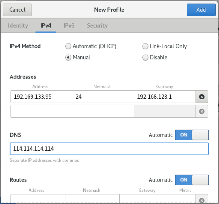
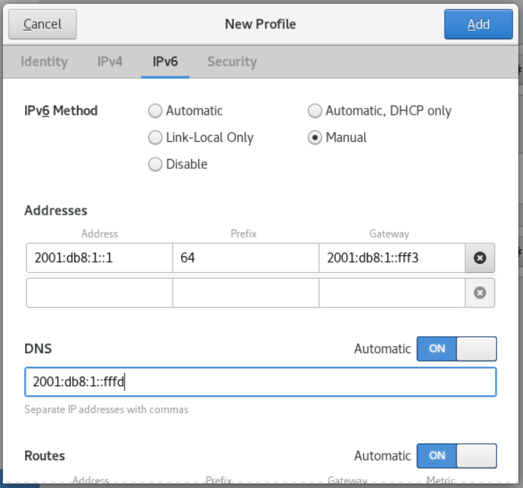
- On the IPv6 tab, configure the IPv6 settings. For example, select the method Manual to set a static IPv6 address, netmask, default gateway, and DNS server:
- Click the Add button to save the connection. GNOME control-center automatically activates the connection.
Verify
- Displays the status of devices and connections:
# nmcli device status
DEVICE      TYPE      STATE      CONNECTION
enp7s0      ethernet  connected  Example-Connection
# nmcli connection show Example-Connection
connection.id:              Example-Connection
connection.uuid:            b6cdfa1c-e4ad-46e5-af8b-a75f06b79f76
connection.stable-id:       --
connection.type:            802-3-ethernet
connection.interface-name:  enp7s0
...
-
Find an IP address in the same subnet. IPv4:
# ping 192.0.2.3IPv6:# ping 2001:db8:1::2``` - Find an IP address in a remote subnet. IPv4:
# ping 192.0.2.3IPv6:
# ping 2001:db8:2::1- If the command fails, ping the default gateway is used to verify the Settings. IPv4:
# ping 192.0.2.254IPv6:
4. Run the host command to verify that domain name resolution is normal:# ping 2001:db8:1::fff3
# host client.test.com
If the command is wrong, such as connection timed out or no servers could be reached, verify your DNS Settings.
Troubleshooting Steps
If the connection fails, or the network interface toggles between the up and down states:
- Make sure the network cable is plugged into the host and switch.
- Check if the connection failure exists only on this host, or other hosts connected to the same switch that this server is connected to.
- Verify that the network cables and network interfaces are working as expected. Perform hardware diagnostic steps and replace defective cables and network interface cards.
- If the configuration on disk does not match the configuration in the device, starting or restarting NetworkManager creates an in-memory connection representing the device's configuration.
8.12. Configure Ethernet connection using nm-connection-editor
Prerequisites
- There is a physical or virtual Ethernet device in the server configuration.
- GNOME is installed.
Process
- Enter in the terminal:
$ nm-connection-editor
-
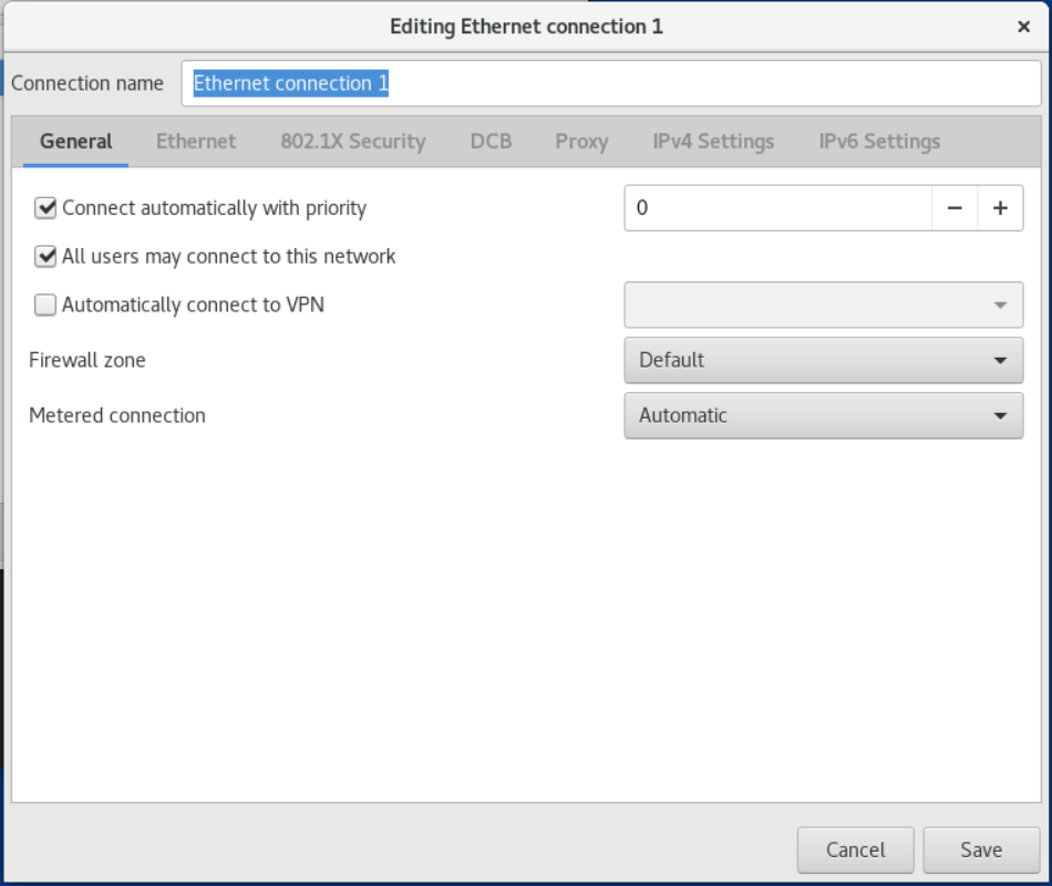
To enable this connection automatically at system startup or when the NetworkManager service is restarted:
- Select Connect automatically with priority.
- Optional: Change the priority value next to Connect automatically with priority.
If there are multiple connection profiles for the same device, NetworkManager only enables one profile. By default, NetworkManager activates the last used profile with autoconnect enabled. However, if you set a priority value in a configuration set, NetworkManager activates the configuration set with the highest priority. 2. If the profile should only be available to the user who created the connection profile, clear the All users may connect to this network check box.
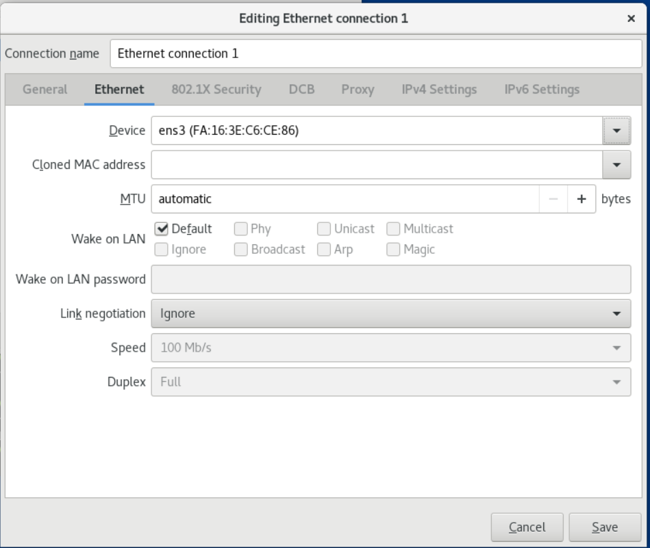
 5. On the Ethernet tab, select a device and optionally select other settings related to Ethernet.
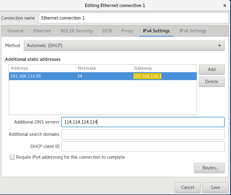
 6. On the IPv4 Settings tab, configure the IPv4 settings. For example, to set a static IPv4 address, netmask, default gateway and DNS server:
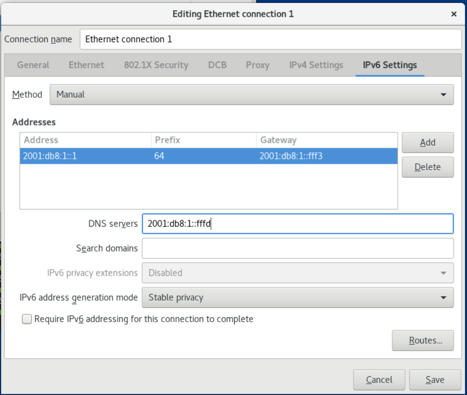
 7. On the IPv6 Settings tab, configure the IPv6 settings. For example, to set a static IPv6 address, netmask, default gateway and DNS server:
 8. Save the connection.
9. Close nm-connection-editor.
8. Save the connection.
9. Close nm-connection-editor.
Verify
-
Use the ping program to verify network connectivity.
-
Find IP addresses on the same subnet. IPv4:
# ping 192.0.2.3IPv6:# ping 2001:db8:1::2- Look up IP addresses in remote subnets. IPv4:# ping 198.162.3.1IPv6:
# ping 2001:db8:2::1- If the command fails, ping the default gateway to verify the settings. IPv4:
# ping 192.0.2.254IPv6:
- Use the host command to verify whether the domain name resolution is normal:# ping 2001:db8:1::fff3
# host client.test.com
If the command is wrong, such as connection timed out or no servers could be reached, verify your DNS settings.
8.13. Change NetworkManager's DHCP client
By default, NetworkManager uses its internal DHCP client. However, if you need a DHCP client that does not provide a built-in client, you can also configure NetworkManager to use dhclient.
Process
- Create the /etc/NetworkManager/conf.d/dhcp-client.conf file:
[main]
dhcp=dhclient
You can set the dhcp parameter to internal (default) or dhclient. 2. If you set the dhcp parameter for dhclient, install the dhcp-client package:
# yum install dhcp-client
# systemctl restart NetworkManager
Note that restarting temporarily interrupts all network connections.
Verify
- Search for entries similar to the following in the /var/log/messages log file:
Sep 5 06:41:52 server NetworkManager[27748]: <info> [1650959659.8483] dhcp-init: Using DHCP client 'dhclient'
This log entry confirms that NetworkManager is using dhclient as the DHCP client.
8.14. Configuring DHCP behavior for NetworkManager connections
A DHCP client requests a dynamic IP address and corresponding configuration information from a DHCP server each time it connects to the network.
When you configure a connection to retrieve an IP address from a DHCP server, NetworkManager requests an IP address from a DHCP server. By default, the client waits 45 seconds for this request to complete. When a DHCP connection is initiated, the dhcp client requests an IP address from the DHCP server.
Prerequisites
- A connection using DHCP is configured on the host.
Process
- Set the ipv4.dhcp-timeout and ipv6.dhcp-timeout properties. For example, to set both options to 30 seconds, enter:
# nmcli connection modify connection_name ipv4.dhcp-timeout 30 ipv6.dhcp-timeout 30
Also, set the parameter to infinity to configure NetworkManager to not stop trying to request and renew an IP address until it succeeds. 2. Optional: Configure the behavior if NetworkManager does not receive an IPv4 address before timing out:
# nmcli connection modify connection_name ipv4.may-fail value
If the ipv4.may-fail option is set to:
- yes ,the state of the connection depends on the IPv6 configuration:
- If the IPv6 configuration is enabled and successful, NetworkManager activates the IPv6 connection and does not attempt to activate the IPv4 connection.
- If IPv6 configuration is disabled or not configured, the connection will fail.
- no , the connection will be stopped. in this case:
- If the connection's autoconnect property is enabled, NetworkManager tries to activate the connection as many times as the value set in the autoconnect-retries property. The default value is 4.
- If the connection still cannot obtain a DHCP address, auto activation will fail. Note that after 5 minutes, the automatic connection process starts again to obtain an IP address from the DHCP server.
- Optional: Configure the behavior if NetworkManager does not receive an IPv6 address before timeout:
# nmcli connection modify connection_name ipv6.may-fail value
8.15. Configuring Multiple Ethernet Interfaces Using a Single Connection Profile by Interface Name
In most cases, a connection profile contains the settings for a network device. However, NetworkManager also supports wildcards when you set interface names in connection profiles. You can use this feature to create a single connection profile that can be used for multiple Ethernet interfaces if the host is roaming between Ethernets with dynamic IP address assignment.
Prerequisites
- DHCP is available in the network
- The host has multiple ethernet adapters
- The connection profile does not exist on the host
Process
- Add a connection profile that can be applied to all interface names starting with enp:
#nmcli connection add con-name Example connection.multi-connect multiple match.interface-name enp* type ethernet
Verify
- Display all settings for a single connection profile:
#nmcli connection show Example
connection.id:                      Example
...
connection.multi-connect:           3 (multiple)
match.interface-name:               `enp*`
...
3 indicates The number of interfaces that are active on the connection profile at the same time , not the number of network interfaces in the connection profile. The connection profile uses all devices that match the pattern in the match.interface-name parameter, so the connection profile has the same universal unique identifier (UUID). 2. Display the status of the connection:
#nmcli connection show
NAME                    UUID                    TYPE     DEVICE
...
Example  6f22402e-c0cc-49cf-b702-eaf0cd5ea7d1  ethernet  enp7s0
Example  6f22402e-c0cc-49cf-b702-eaf0cd5ea7d1  ethernet  enp8s0
Example  6f22402e-c0cc-49cf-b702-eaf0cd5ea7d1  ethernet  enp9s0
8.16. Configure a connection profile for multiple Ethernet interfaces using PCI IDs
A PCI ID is a unique identifier for a device connected to the system. A connection profile adds multiple devices by matching interfaces based on a list of PCI IDs. You can use this process to connect multiple device PCI IDs to a connection profile.
Prerequisites
- A DHCP server is available in the network
- The host has multiple ethernet adapters
- The connection profile does not exist on the system
Process
- Identify the device path. For example, to display device paths for all interfaces beginning with enp, enter:
#udevadm info /sys/class/net/enp* | grep ID_PATH=
...
E: ID_PATH=pci-0000:07:00.0
E: ID_PATH=pci-0000:08:00.0
#nmcli connection add type ethernet connection.multi-connect multiple match.path "pci-0000:07:00.0 pci-0000:08:00.0" con-name Example
Verify
- Display the status of the connection:
#nmcli connection show

NAME   UUID     TYPE        DEVICE
...
Example      9cee0958-512f-4203-9d3d-b57af1d88466  ethernet  enp7s0
Example      9cee0958-512f-4203-9d3d-b57af1d88466  ethernet  enp8s0
...
#nmcli connection show Example

connection.id:               Example
...
connection.multi-connect:    3 (multiple)
match.path:                  pci-0000:07:00.0,pci-0000:08:00.0
...
This connection profile uses all devices whose PCI ID matches the pattern in the match.path parameter, so the connection profile has the same universally unique identifier (UUID).
Chapter 9 Managing Wi-Fi Connections
9.1. Use nmcli to configure Wi-Fi connection
Prerequisites
- The nmcli tool is installed.
- Make sure WiFi is enabled:
Process
- Create a Wi-Fi connection profile with a static IP configuration:
$ nmcli con add con-name MyCafe ifname wlan0 type wifi ssid MyCafe ip4 192.0.2.101/24 gw4 192.0.2.1
$ nmcli con modify con-name MyCafe ipv4.dns "192.0.2.1"
$ nmcli con modify con-name MyCafe ipv4.dns-search "example.com"
$ nmcli connection show id MyCafe | grep mtu
802-11-wireless.mtu:                     auto
$ nmcli connection modify id MyCafe wireless.mtu 1350
$ nmcli connection show id MyCafe | grep mtu
802-11-wireless.mtu:                     1350
Verify
-
Use the ping command to verify whether the wifi network is connected::
-
same subnet:
# ping 192.0.2.103If the command fails, verify the IP and subnet settings. - Extranet:
# ping 198.51.16.3- If the command fails, ping the default gateway to verify the settings.
2. Use the host command to verify whether the domain name resolution is normal.# ping 192.0.2.1
# host client.example.com
If the command returns any errors, such as connection timed out or no servers could be reached, verify your DNS settings.
9.2. Use control-center to configure Wi-Fi connection
process
- Go to Settings and select the WI-FI option in the left menu bar to see the available Wi-Fi networks.
- Select the gear wheel icon to the right of the name of the Wi-Fi connection you want to edit and the Edit Connection dialog will appear. The Details menu window displays connection details that you can further configure.
Options
- If you select "Connect automatically", NetworkManager will automatically connect to the connection when NetworkManager detects that it is available. Clear the check box if you do not want NetworkManager to connect automatically. Note that when the check box is cleared, you must select the connection in the network connection icon's menu to make it connect.
- To make the connection available to other users, select the Make available to other users check box.
- You can also control background data usage by changing Restrict background data usage.
- Select the Identity menu item to view basic configuration options.
SSID - The Service Set Identifier (SSID) of the Access Point (AP).
BSSID - The Basic Service Set Identifier (BSSID) is the MAC address (also known as the hardware address) of the specific wireless access point you are connecting to in infrastructure mode. By default, this field is blank and you can connect to a wireless access point by SSID without specifying a BSSID. If a BSSID is specified, it will force the system to only associate to a specific access point. For ad-hoc networks, the BSSID is randomly generated by the mac80211 subsystem when the ad-hoc network is created. NetworkManager doesn't show it.
MAC Address - A MAC address allows you to associate a specific wireless adapter with a specific connection (or connections).
Clone Address - Uses a cloned MAC address instead of the actual hardware address. Leave blank unless required. 4. For further IP address configuration, select the IPv4 and IPv6 menu item.
By default, both IPv4 and IPv6 are set to auto-configure based on the current network settings. This means that when the interface is connected to the network, the local IP address, DNS address and other settings are automatically detected. If a DHCP server assigns the IP configuration in this network, but you can also provide static configuration in IPv4 and IPv6 settings. In the IPv4 and IPv6 menu entries you can see the following settings:
-
IPv4
- Automatic (DHCP) - select this option if the network you are connecting to uses a Router Advertisement (RA) or DHCP server to assign dynamic IP addresses. You can see the assigned IP address in the Details menu entry.
- Link Only - Select this option if the network you are connecting to does not have a DHCP server and you do not want to assign IP addresses manually. Random addresses will be assigned a prefix of 169.254/16 according to RFC 3927.
- Manual - Select this option if you want to assign IP addresses manually.
- disable - IPv4 is disabled for this connection.
-
DNS
-
If Automatic is ON and there is no DHCP server available to assign a DNS server for this connection, switch it to OFF to enter the IP addresses of the DNS servers separated by commas.
- Routes
Note that in the Routes section, when Automatic is ON, routes from Router Advertisement (RA) or DHCP are used, but you can also add additional static routes. When OFF, only static routes are used.
- Address - Enter the IP address of the remote network, subnet, or host.
- Subnet Mask - The subnet mask or prefix length for the IP address entered above.
- Gateway - The IP address of the gateway for the remote network, subnetwork, or host entered above.
- metric - network cost, the preferred value given to this route. The lower the number, the higher the priority.
-
Use this connection only for resources on their network
- use this connection only for resources on its network
- Select this checkbox to prevent the connection from being the default route.
-
IPv6
- Automatic—Select this option to use IPv6 Stateless Address Autoconfiguration (SLAAC) to create an automatic stateless configuration based on hardware addresses and Router Advertisements (RAs).
- Automatic, DHCP Only - Select this option to not use RA and instead request information directly from DHCPv6 to create a stateful configuration.
- Link Only - Select this option if the network you are connecting to does not have a DHCP server and you do not want to assign IP addresses manually. Random addresses will be assigned according to RFC 4862 with a prefix of FE80::0.
- Manual - Select this option if you want to assign IP addresses manually.
- disable - IPv6 is disabled for this connection.
-
Select the Security menu item to configure the security settings.
-
safety
- None - encryption is disabled, data is transmitted in plain text across the network.
- WEP 40/128 bit key - Wired Equivalent Privacy (WEP), from the IEEE 802.11 standard. Use a single pre-shared key (PSK).
- WEP 128-bit passphrase - MD5 hash of the passphrase used to generate the WEP key.
- Dynamic WEP(802.1X) - WEP key changes dynamically.
- LEAP - Lightweight Extensible Authentication Protocol for Cisco Systems.
- WPA and WPA2 Personal - Wi-Fi Protected Access (WPA) from the IEEE 802.11i draft standard. Wi-Fi Protected Access 2 (WPA2) from the 802.11i-2004 standard. Personal mode, using a pre-shared key (WPA-PSK).
- WPA & WPA2 Enterprise—WPA and WPA2 are used with RADIUS authentication servers to provide IEEE 802.1X network access control.
- WPA3 Personal - Wi-Fi Protected Access 3 (WPA3) Personal uses Simultaneous Authentication of Equals (SAE) instead of Pre-Shared Key (PSK) to prevent dictionary attacks. WPA3 uses perfect forward secrecy.
- password
- Enter the password to be used during the verification process.
- After completing the configuration, click the Apply button to save the configuration.
9.3. Connect to Wi-Fi network using nmcli
Prerequisites
- The nmcli tool is installed.
- Make sure WiFi is enabled (default):
$ nmcli radio wifi on
Process
- Refresh the list of available Wi-Fi connections:
$ nmcli device wifi rescan
$ nmcli dev wifi list

IN-USE  SSID      MODE   CHAN  RATE        SIGNAL  BARS  SECURITY
...
        MyCafe    Infra  3     405 Mbit/s  85      ▂▄▆█  WPA1 WPA2
$ nmcli dev wifi connect SSID-Name password wireless-password
例如:
$ nmcli dev wifi connect MyCafe password wireless-password
禁用 Wi-Fi :
$ nmcli radio wifi off
9.4. Connect to a hidden Wi-Fi network using nmcli
All Wi-Fi access points have a Service Set Identifier (SSID) to identify them. However, an access point can be configured not to broadcast its SSID, in which case it will be hidden and not appear in NetworkManager's list of available networks.
Prerequisites
- The nmcli tool is installed.
- Know the SSID, and password for your Wi-Fi connection.
- Make sure WiFi is enabled (default):
$ nmcli radio wifi on
Process
- Connect to a hidden SSID:
$ nmcli dev wifi connect SSID_Name password wireless_password hidden yes
9.5. Connect to Wi-Fi network using GNOME GUI
Process
- Open the GNOME Shell network connections icon menu in the upper right corner of the screen.
- Select Wi-Fi Not Connected.
- Click the Select Network option.
- Click the name of the network you want to connect to, and then click Connect.
Note that if you do not see the network, it may be hidden.
- If a password or encryption key is required to secure the network, enter the password and click Connect.
Please note: If you do not know the password, please contact the administrator of the Wi-Fi network.
- If the connection is successful, you will see the network connection in the connection icon menu, the WiFi icon is located in the upper right corner of the screen.
9.6. Configure 802.1X network authentication on an existing Wi-Fi connection using nmcli
Using the nmcli tool, you can configure network authentication. This procedure describes how to configure Protected Extensible Authentication Protocol (PEAP) authentication using Microsoft Challenge-Handshake Authentication Protocol version 2 (MSCHAPv2) in an existing NetworkManager Wi-Fi connection profile named wlp1s0.
Prerequisites
- The network must have 802.1X network authentication.
- A Wi-Fi connection profile exists in NetworkManager and has a valid IP configuration.
- If the client is required to verify the authenticator's certificate, the Certificate Authority (CA) certificate must be stored in the /etc/pki/ca-trust/source/anchors/ directory.
- The wpa_supplicant package is installed.
Process
- Set the Wi-Fi security mode to wpa-eap, set the Extensible Authentication Protocol (EAP) to peap, set the internal authentication protocol to mschapv2, and set the username:
# nmcli connection modify wlp1s0 wireless-security.key-mgmt wpa-eap 802-1x.eap peap 802-1x.phase2-auth mschapv2 802-1x.identity user_name
Note that you must set the wireless-security.key-mgmt, 802-1x.eap, 802-1x.phase2-auth, and 802-1x.identity parameters in a single command. 2. Alternatively, store the password in the configuration:
# nmcli connection modify wlp1s0 802-1x.password password
By default, NetworkManager saves passwords in clear text in the /etc/sysconfig/network-scripts/keys-connection_name file, which is only readable by the root user. However, clearing text passwords in configuration files has security implications.
For increased security, set the 802-1x.password-flags parameter to 0x1. With this setup, on servers with the GNOME desktop environment or running nm-applet, NetworkManager retrieves passwords from these services. In other cases, NetworkManager will prompt for a password. 3. If you want the client to verify the authenticator's certificate, set the 802-1x.ca-cert parameter in the connection configuration file to the path to the CA certificate:
# nmcli connection modify wlp1s0 802-1x.ca-cert /etc/pki/ca-trust/source/anchors/ca.crt
# nmcli connection up wlp1s0
Chapter 10 Configuring VLAN Tags
This chapter discusses how to configure virtual local area networks (VLANs). A VLAN is a logical network within a physical network. When the packet passes through the VLAN interface, it will carry the interface tag and VLAN ID, and the tag will be removed when the packet returns.
You can create a VLAN interface on another interface such as an Ethernet, bond, team, or bridge device. This interface is called the parent interface.
10.1. Use the nmcli command to configure VLAN tags
Prerequisites
- The parent interface that you plan to use as the virtual VLAN interface supports VLAN tagging.
-
If you configure VLANs on bonded interfaces:
-
The bound port is online.
- This binding is not configured with the fail_over_mac=follow option. A VLAN virtual device cannot change its MAC address to match the new MAC address of the parent device. In this case, traffic is still sent with the incorrect source MAC address.
- This binding normally does not expect to obtain an IP address from a DHCP server or IPv6 autoconfiguration. Set the ipv4.method=disable and ipv6.method=ignore options when creating the binding. Otherwise, the interface might go down if DHCP or IPv6 autoconfiguration fails after a period of time.
- The switch to which the host is connected is configured to support VLAN tagging. See your switch instructions for details.
Process
- Show network interfaces:
# nmcli device status
DEVICE   TYPE      STATE         CONNECTION
enp1s0   ethernet  disconnected  enp1s0
bridge0  bridge    connected     bridge0
bond0    bond      connected     bond0
...
# nmcli connection add type vlan con-name vlan10 ifname vlan10 vlan.parent enp1s0 vlan.id 10
Note that VLAN must be in the range 0 to 4094. 3. By default, VLAN attachments inherit the Maximum Transmission Unit (MTU) of the parent interface. Alternatively, a different MTU value can be set:
# nmcli connection modify vlan10 ethernet.mtu 2000
-
Configure the IPv4 settings. For example, to set a static IPv4 address, netmask, default gateway, and DNS server settings for a vlan10 connection, enter:
2. Configure the IPv6 settings. For example, to set a static IPv6 address, netmask, default gateway, and DNS server settings for a vlan10 connection, enter:# nmcli connection modify vlan10 ipv4.addresses '192.0.2.1/24' # nmcli connection modify vlan10 ipv4.gateway '192.0.2.254' # nmcli connection modify vlan10 ipv4.dns '192.0.2.253' # nmcli connection modify vlan10 ipv4.method manual5. To activate the connection:# nmcli connection modify vlan10 ipv6.addresses '2001:db8:1::1/32' # nmcli connection modify vlan10 ipv6.gateway '2001:db8:1::fffe' # nmcli connection modify vlan10 ipv6.dns '2001:db8:1::fffd' # nmcli connection modify vlan10 ipv6.method manual
# nmcli connection up vlan10
Verify
- Verify the configuration:
# ip -d addr show vlan10
4: vlan10@enp1s0: <BROADCAST,MULTICAST,UP,LOWER_UP> mtu 1500 qdisc noqueue state UP group default qlen 1000
    link/ether 52:54:00:72:2f:6e brd ff:ff:ff:ff:ff:ff promiscuity 0
    vlan protocol 802.1Q id 10 <REORDER_HDR> numtxqueues 1 numrxqueues 1 gso_max_size 65536 gso_max_segs 65535
    inet 192.0.2.1/24 brd 192.0.2.255 scope global noprefixroute vlan10
    valid_lft forever preferred_lft forever
    inet6 2001:db8:1::1/32 scope global noprefixroute
    valid_lft forever preferred_lft forever
    inet6 fe80::8dd7:9030:6f8e:89e6/64 scope link noprefixroute
    valid_lft forever preferred_lft forever
10.2. Configure VLAN tags using nm-connection-editor
Prerequisites
- The parent interface that you plan to use as the virtual VLAN interface supports VLAN tagging.
-
If you configure VLANs on bonded interfaces:
-
The bound port is online.
- This binding is not configured with the fail_over_mac=follow option. A VLAN virtual device cannot change its MAC address to match the new MAC address of the parent device. In this case, traffic is still sent with the incorrect source MAC address.
- The switch to which the host is connected is configured to support VLAN tagging. See your switch instructions for details.
Process
- Open the terminal and enter nm-connection-editor :
$ nm-connection-editor
- Select the higher-level interface.
- Select a VLAN ID. Note that VLAN must be in the range 0 to 4094.
- By default, VLAN attachments inherit the Maximum Transmission Unit (MTU) of the parent interface. In addition, different MTU values can be set.
- Optionally, set the name of the VLAN interface and other VLAN-specific options.
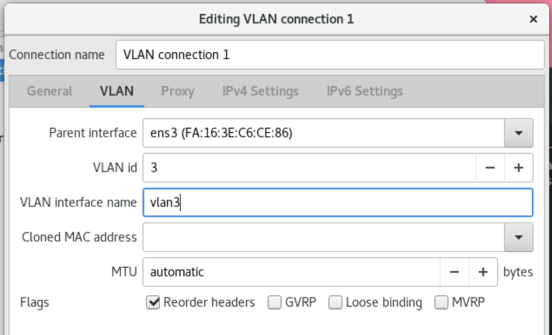
- Configure the IP settings of the VLAN device. If you want to use this VLAN device as the port of other devices, please skip this step.
- On the IPv4 Settings tab, configure the IPv4 settings. For example, to set a static IPv4 address, netmask, default gateway and DNS server:
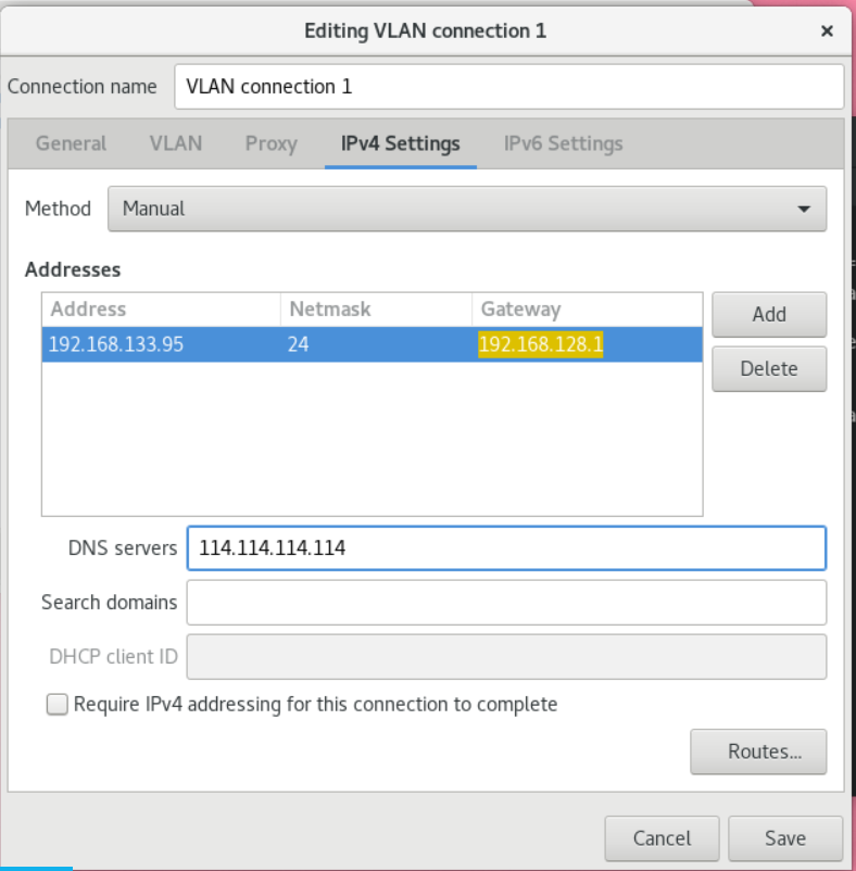
- On the IPv6 Settings tab, configure the IPv6 settings. For example, to set a static IPv6 address, netmask, default gateway and DNS server:
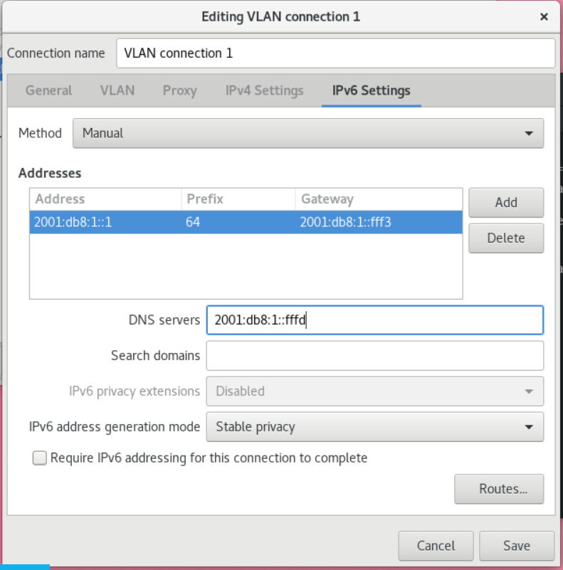
- Click Save to save the VLAN connection.
- Close nm-connection-editor.
Verify
- Verify the configuration:
# ip -d addr show vlan3
4: vlan3@ens3: <BROADCAST,MULTICAST,UP,LOWER_UP> mtu 1500 qdisc noqueue state UP group default qlen 1000
    link/ether 52:54:00:d5:e0:fb brd ff:ff:ff:ff:ff:ff promiscuity 0
    vlan protocol 802.1Q id 10 <REORDER_HDR> numtxqueues 1 numrxqueues 1 gso_max_size 65536 gso_max_segs 65535
    inet 192.0.2.1/24 brd 192.0.2.255 scope global noprefixroute vlan10
    valid_lft forever preferred_lft forever
    inet6 2001:db8:1::1/32 scope global noprefixroute
    valid_lft forever preferred_lft forever
    inet6 fe80::8dd7:9030:6f8e:89e6/64 scope link noprefixroute
    valid_lft forever preferred_lft forever
10.3. Configuring VLAN tagging with nmstatectl
This section describes how to use the nmstatectl tool to configure a VLAN with ID 10 using an Ethernet connection. As a sub-device, VLAN attachments contain IP, default gateway, and DNS configurations.
Depending on your environment, adjust the YAML file accordingly. For example, to use a bridge or bonded device in a VLAN, adjust the base-iface and type attributes of the ports you use in the VLAN.
Prerequisites
- To use an Ethernet device as a port in a VLAN, a physical or virtual Ethernet device must be installed in the server.
- The nmstate package is installed.
Process
- Create a YAML file containing the following content, ~/create-vlan.yml:
---
interfaces:
- name: vlan10
type: vlan
state: up
ipv4:
    enabled: true
    address:
    - ip: 192.0.2.1
    prefix-length: 24
    dhcp: false
ipv6:
    enabled: true
    address:
    - ip: 2001:db8:1::1
    prefix-length: 64
    autoconf: false
    dhcp: false
vlan:
    base-iface: enp1s0
    id: 10
- name: enp1s0
type: ethernet
state: up

routes:
config:
- destination: 0.0.0.0/0
    next-hop-address: 192.0.2.254
    next-hop-interface: vlan10
- destination: ::/0
    next-hop-address: 2001:db8:1::fffe
    next-hop-interface: vlan10

dns-resolver:
config:
    search:
    - example.com
    server:
    - 192.0.2.200
    - 2001:db8:1::ffbb
# nmstatectl apply ~/create-vlan.yml
Verify
- Display the status of the device and the connection:
# nmcli device status
DEVICE      TYPE      STATE      CONNECTION
vlan10      vlan      connected  vlan10
# nmcli connection show vlan10
connection.id:              vlan10
connection.uuid:            1722970f-788e-4f81-bd7d-a86bf21c9df5
connection.stable-id:       --
connection.type:            vlan
connection.interface-name:  vlan10
...
# nmstatectl show vlan0
10.4. Configure VLAN tags using rhel-system-roles
This section describes how to add a VLAN with Ethernet connection ID 10 on top of this Ethernet connection. As a sub-device, VLAN attachments contain IP, default gateway, and DNS configurations.
Depending on your environment, adjust accordingly. For example:
To use the VLAN as a port in other connections (such as bonding), omit the ip attribute and set the IP configuration in the subconfiguration.
To use a team, bridge, or bond device in a VLAN, adjust the interface_name and type properties of the port you are using in the VLAN.
Prerequisites
- Ansible and rhel-system-roles packages are installed on the control node.
- If you are using a non-root user when running the playbook, make sure this user has sudo privileges on the node.
Process
- If the host you want to execute the playbook on is not already listed, add the host's IP or name to the /etc/ansible/hosts Ansible inventory file:
node.example.com
---
- name: Configure a VLAN that uses an Ethernet connection
  hosts: node.example.com
  become: true
  tasks:
  - include_role:
      name: rhel-system-roles.network

    vars:
      network_connections:
        # Add an Ethernet profile for the underlying device of the VLAN
        - name: enp1s0
          type: ethernet
          interface_name: enp1s0
          autoconnect: yes
          state: up
          ip:
            dhcp4: no
            auto6: no

        # Define the VLAN profile
        - name: enp1s0.10
          type: vlan
          ip:
            address:
              - "192.0.2.1/24"
              - "2001:db8:1::1/64"
            gateway4: 192.0.2.254
            gateway6: 2001:db8:1::fffe
            dns:
              - 192.0.2.200
              - 2001:db8:1::ffbb
            dns_search:
              - example.com
          vlan_id: 10
          parent: enp1s0
          state: up
The parent attribute in the VLAN configuration file configures the VLAN to run on top of the enp1s0 device. 3. Run the playbook:
- To connect to a managed host as root, enter:
# ansible-playbook -u root ~/vlan-ethernet.yml
# ansible-playbook -u user_name --ask-become-pass ~/vlan-ethernet.yml
The --ask-become-pass option ensures that the ansible-playbook command prompts for the sudo password for the user defined in the -u user_name option.
If the -u user_name option is not specified, ansible-playbook connects to the managed host as the user currently logged into the control node.
Chapter 11 Creating Virtual Layer 2 Domains for Virtual Machines Using VXLAN
Virtual Extensible LAN (VXLAN) is a network protocol that tunnels Layer 2 traffic over an IP network using the UDP protocol. For example, some virtual machines (VMs) running on different hosts can communicate through VXLAN tunnels. Hosts can be on different subnets, or even in different data centers around the world. From the perspective of the virtual machine, other virtual machines in the same VXLAN are in the same layer 2 domain.
This document describes how to configure VM-invisible VXLAN on an OpenCLoudOS host: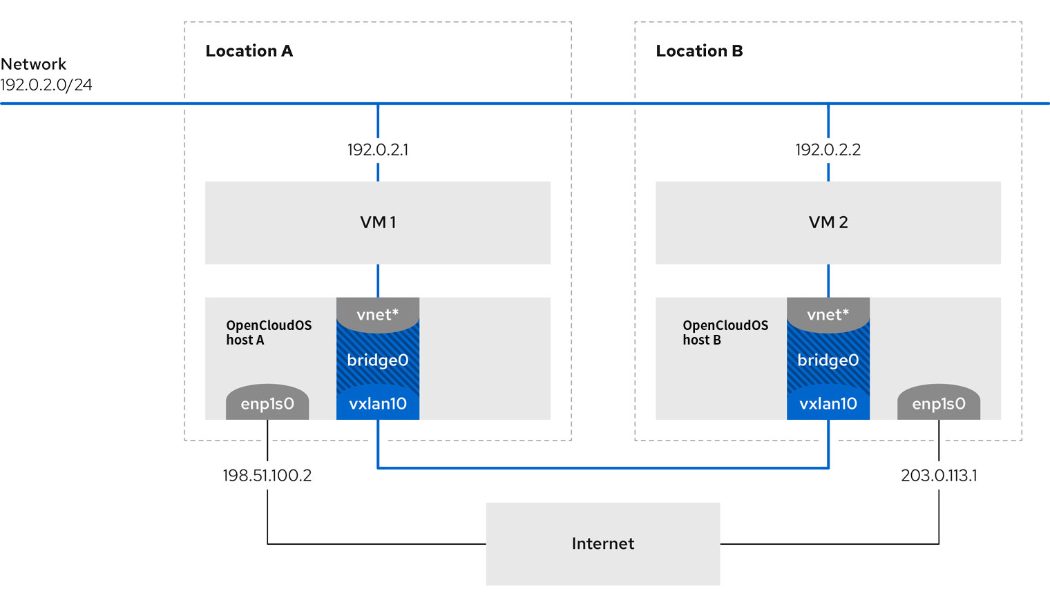
In this example, OpenCloudOS-host-A and OpenCloudOS-host-B use bridge br0 to connect the virtual machines' virtual networks on each host with VXLAN vxlan10. Due to this configuration, VXLAN is invisible to the virtual machine and the virtual machine does not require any special configuration. If you later connect more virtual machines to the same virtual network, the virtual machines will automatically become members of the same virtual layer 2 domain.
Data in VXLAN is not encrypted just like normal Layer 2 traffic. For security reasons, use VXLAN over VPN or other types of encrypted connections.
11.1. Advantages of VXLAN
Virtual Extensible LAN (VXLAN) offers the following key benefits:
- VXLAN uses 24-bit IDs. Therefore, you can create up to 16,777,216 isolated networks. For example, virtual LANs (VLANs) only support 4,096 isolated networks.
- VXLAN uses the IP protocol. This allows you to control traffic through routing and run systems virtually on different networks and locations within the same Layer 2 domain.
- Unlike most tunneling protocols, VXLAN is not just a point-to-point network. VXLAN can learn the IP addresses of other endpoints dynamically, or it can use statically configured forwarding entries.
- Some NICs support UDP tunnel related offload functionality.
11.2. Configure the Ethernet interface on the host
To connect an OpenCloudOS virtual machine host to Ethernet, create a network connection profile, configure IP settings, and activate the profile.
Run this procedure on the OpenCloudOS host and adjust the IP address configuration accordingly.
Prerequisites
- The host is connected to the Ethernet host.
Process
- Add a new Ethernet connection profile in NetworkManager:
# nmcli connection add con-name Example ifname enp1s0 type ethernet
# nmcli connection modify Example ipv4.addresses 198.51.100.2/24 ipv4.method manual ipv4.gateway 198.51.100.254 ipv4.dns 198.51.100.200 ipv4.dns-search example.com
Skip this step if your network uses DHCP. 3. Activate the Example connection:
# nmcli connection up Example
Verify
- Display the status of the device and the connection:
# nmcli device status
DEVICE      TYPE      STATE      CONNECTION
enp1s0      ethernet  connected  Example
# ping OpenCloudOS-host-B.example.com
Note that you cannot ping other virtual machine hosts until networking is configured on that host.
11.3. Create a bridge with VXLAN attached
To make Virtual Extensible LAN (VXLAN) invisible to virtual machines (VMs), create a bridge on the host and attach VXLAN to the bridge. Use NetworkManager to create bridges and VXLANs. You cannot add any traffic access point (TAP) devices (often called vnet* on the host machine) of virtual machines to the bridge. They are added dynamically by the libvirtd service when the virtual machine starts.
Run this procedure on the OpenCloudOS host and adjust the IP address accordingly.
Process
- Create bridge br0:
# nmcli connection add type bridge con-name br0 ifname br0 ipv4.method disabled ipv6.method disabled
This command sets no IPv4 and IPv6 addresses on the bridge device because the bridge works at layer 2. 2. Create a VXLAN interface and attach it to br0:
# nmcli connection add type vxlan slave-type bridge con-name br0-vxlan10 ifname vxlan10 id 10 local 198.51.100.2 remote 203.0.113.1 master br0
This command uses the following settings:
- ID 10 : Set the VXLAN identifier.
- local 198.51.100.2 : Sets the source IP address of outgoing packets.
- remote 203.0.113.1 : Sets the unicast or multicast IP address to use in outgoing packets when the destination link-layer address is unknown in the VXLAN device forwarding database.
- remote 203.0.113.1 : Sets the unicast or multicast IP address to use in outgoing packets when the destination link-layer address is unknown in the VXLAN device forwarding database.
- ipv4.method disabled and ipv6.method disabled: Disable IPv4 and IPv6 on the bridge.
- Activate the br0 connection profile:
# nmcli connection up br0
# nmcli connection up br0
Verify
- show forwarding table:
# bridge fdb show dev vxlan10
2a:53:bd:d5:b3:0a master br0 permanent
00:00:00:00:00:00 dst 203.0.113.1 self permanent
...
11.4. Create a virtual network in libvirt with an existing bridge
To enable a virtual machine (VM) to use the br0 bridge with Virtual Extensible LAN (VXLAN) attached, first add a virtual network to the libvirtd service that uses this bridge.
Prerequisites
- You have installed the libvirt package.
- You have installed the libvirt package.
- You have configured a br0 device with VXLAN on OpenCloudOS.
Process
- Create a ~/vxlan10-bridge.xml file with the following content:
<network><name>vxlan10-bridge</name><forward mode="bridge" /><bridge name="br0" /></network>
# virsh net-define ~/vxlan10-bridge.xml
# rm ~/vxlan10-bridge.xml
# virsh net-start vxlan10-bridge
# virsh net-autostart vxlan10-bridge
Verify
- Display a list of virtual networks:
# virsh net-list
Name              State    Autostart   Persistent
----------------------------------------------------
vxlan10-bridge    active   yes         yes
...
11.5. Configuring Virtual Machines to Use VXLAN
To configure a virtual machine on a host to use a bridge device with an attached Virtual Extensible LAN (VXLAN), create a new virtual machine that uses the vxlan10-bridge virtual network or update the settings of an existing virtual machine to use this network .
Prerequisites
- You configured the vxlan10-bridge virtual network in libvirtd.
Process
- To create a new virtual machine and configure it to use the vxlan10-bridge network, pass the --network network:vxlan10-bridge option to the virt-install command when creating the virtual machine:
# virt-install ... --network network:vxlan10-bridge
- Connect the virtual machine's network interface to the vxlan10-bridge virtual network:
# virt-xml VM_name --edit --network network=vxlan10-bridge
# virsh shutdown VM_name
# virsh start VM_name
Verify
- Display the virtual network interfaces of the virtual machines on the host:
# virsh domiflist VM_name
Interface   Type     Source           Model    MAC
-------------------------------------------------------------------
vnet1       bridge   vxlan10-bridge   virtio   52:54:00:c5:98:1c
# ip link show master vxlan10-bridge
18: vxlan10: <BROADCAST,MULTICAST,UP,LOWER_UP> mtu 1500 qdisc noqueue master br0 state UNKNOWN mode DEFAULT group default qlen 1000
    link/ether 2a:53:bd:d5:b3:0a brd ff:ff:ff:ff:ff:ff
19: vnet1: <BROADCAST,MULTICAST,UP,LOWER_UP> mtu 1500 qdisc noqueue master br0 state UNKNOWN mode DEFAULT group default qlen 1000
    link/ether 52:54:00:c5:98:1c brd ff:ff:ff:ff:ff:ff
Note that the libvirtd service dynamically updates the configuration of the bridge. When you start a virtual machine that uses the vxlan10-bridge network, the corresponding vnet* device on the host will appear as the port of the bridge. 3. Use Address Resolution Protocol (ARP) requests to verify that the virtual machines are in the same VXLAN:
- Start two or more virtual machines in the same VXLAN.
-
Send an ARP request from one virtual machine to another:
 # arping -c 1 192.0.2.2
 ARPING 192.0.2.2 from 192.0.2.1 enp1s0
 Unicast reply from 192.0.2.2 [52:54:00:c5:98:1c] 1.450ms
 Sent 1 probe(s) (0 broadcast(s))
 Received 1 response(s) (0 request(s), 0 broadcast(s))
If the command displays a reply, then the virtual machines are in the same Layer 2 domain, in this case, the same VXLAN.
Install the iputils package to use the arping tool.
Chapter 12 Configuring Network Bridging
A network bridge is a link-layer device that forwards traffic between networks based on a list of MAC addresses. Bridges build MAC address tables by listening to network traffic and learning about the hosts connected to each network. For example, you can use software bridging on an OpenCLoudOS host to emulate hardware bridging or in a virtualized environment to integrate virtual machines (VMs) into the same network as the host.
Bridging requires a network device in each network that the bridge should connect to. When you configure a bridge, the bridge is called a controller, which is a device that uses ports.
You can create bridges in different types of devices, such as:
- Physical and virtual Ethernet devices
- network binding
- Network team (team)
- VLAN devices
Since the IEEE 802.11 standard specifies the use of 3 address frames in Wi-Fi to effectively use random time, you cannot configure a bridge over a Wi-Fi network in Ad-Hoc or Infrastructure mode.
12.1. Use the nmcli command to configure network bridging
Prerequisites
- Install two or more physical or virtual network devices in the server.
- To use an Ethernet device as a port of a bridge, a physical or virtual Ethernet device must be installed in the server.
- To use team, bond, or VLAN devices as ports for the bridge, you can create these devices when creating the bridge, or create them beforehand.
Process
- Create a bridge interface:
# nmcli connection add type bridge con-name bridge0 ifname bridge0
This command creates a bridge named bridge0. 2. Display the network interfaces, and note the name of the interface you want to add to the bridge:
# nmcli device status
DEVICE  TYPE      STATE         CONNECTION
enp7s0  ethernet  disconnected  --
enp8s0  ethernet  disconnected  --
bond0   bond      connected     bond0
bond1   bond      connected     bond1
...
In this example:
- enp7s0 and enp8s0 are not configured. To use these devices as ports, add a connection profile in the next step.
- bond0 and bond1 already have connection profiles. To use these devices as ports, modify their configuration sets in the next step.
-
Assign the interface to the bridge.
-
If the interface you want to assign to the bridge is not configured, create a new connection profile for it:
2. If you want to assign existing connection profiles to bridges, set the master parameter of these connections to bridge0:# nmcli connection add type ethernet slave-type bridge con-name bridge0-port1 ifname enp7s0 master bridge0 # nmcli connection add type ethernet slave-type bridge con-name bridge0-port2 ifname enp8s0 master bridge0# nmcli connection modify bond0 master bridge0 # nmcli connection modify bond1 master bridge0These commands assign the existing connection profiles named bond0 and bond1 to the bridge0 connection. 4. Configure the IP settings for the bridge. Skip this step if you want to use this bridge as a port for other devices.
-
Configure the IPv4 settings. Example: To set a static IPv4 address, netmask, default gateway, DNS server, and DNS search domain for the bridge0 connection, enter:
- Configure the IPv6 settings. Example: To set a static IPv6 address, netmask, default gateway, DNS server, and DNS search domain for the bridge0 connection, enter:
- Optional: Configure other properties of the bridge. For example, to set the Spanning Tree Protocol (STP) priority of bridge0 to 16384, enter:
- Activate the connection:
# nmcli connection up bridge0
# nmcli device
DEVICE   TYPE      STATE      CONNECTION
...
enp7s0   ethernet  connected  bridge0-port1
enp8s0   ethernet  connected  bridge0-port2
When you activate any port connected, NetworkManager also activates the bridge, but not its other ports. You can configure Red Hat Enterprise Linux to automatically enable all ports when bridging is enabled:
-
Enable the connection.autoconnect-slaves parameter for the bridge connection:
2. Reactivate the bridge:# nmcli connection modify bridge0 connection.autoconnect-slaves 1# nmcli connection up bridge0
Verify
- Use the ip tool to display the link status of the ethernet device as a specific bridge port:
# ip link show master bridge0
3: enp7s0: <BROADCAST,MULTICAST,UP,LOWER_UP> mtu 1500 qdisc fq_codel master bridge0 state UP mode DEFAULT group default qlen 1000
    link/ether 52:54:00:62:61:0e brd ff:ff:ff:ff:ff:ff
4: enp8s0: <BROADCAST,MULTICAST,UP,LOWER_UP> mtu 1500 qdisc fq_codel master bridge0 state UP mode DEFAULT group default qlen 1000
    link/ether 52:54:00:9e:f1:ce brd ff:ff:ff:ff:ff:ff
# bridge link show
3: enp7s0: <BROADCAST,MULTICAST,UP,LOWER_UP> mtu 1500 master bridge0 state forwarding priority 32 cost 100
4: enp8s0: <BROADCAST,MULTICAST,UP,LOWER_UP> mtu 1500 master bridge0 state listening priority 32 cost 100
5: enp9s0: <BROADCAST,MULTICAST,UP,LOWER_UP> mtu 1500 master bridge1 state forwarding priority 32 cost 100
6: enp11s0: <BROADCAST,MULTICAST,UP,LOWER_UP> mtu 1500 master bridge1 state blocking priority 32 cost 100
...
To display the status of a specific Ethernet device, use the bridge link show dev ethernet_device_name command.
12.2. Use nm-connection-editor to configure network bridging
This section describes how to configure the bridge using the nm-connection-editor application. Note that nm-connection-editor can only add new ports to bridges. To use an existing connection profile as a port, use the nmcli tool to create a bridge.
Prerequisites
- Install two or more physical or virtual network devices in the server.
- To use an Ethernet device as a port of a bridge, a physical or virtual Ethernet device must be installed in the server.
- To use team, bond or VLAN devices as bridge ports, make sure those devices are not already configured.
Process
- Open the terminal and enter nm-connection-editor
- Click the + button to add a new connection.
- Select the Bridge connection type and click Create.
-
On the Bridge tab:
-
Optional: Set a name for the bridge interface in the Interface name field.
- Click the Add button to create a new connection profile for the network interface and add the profile as a port to the bridge.
- Select the connection type of the interface. For example, choose Ethernet for a wired connection.
- In addition, a connection name can be set for the port device.
- If you are creating a connection profile for an Ethernet device, open the Ethernet tab, and in the Device field select the network interface you want to add as a port to the bridge. If you selected a different device type, configure it accordingly.
Process
- Open the terminal and enter nm-connection-editor
- Click the + button to add a new connection.
- Select the Bridge connection type and click Create.
- On the Bridge tab:
- Optional: Set a name for the bridge interface in the Interface name field.
- Click the Add button to create a new connection profile for the network interface and add the profile as a port to the bridge.
- Select the connection type of the interface. For example, choose Ethernet for a wired connection.
- In addition, a connection name can be set for the port device.
- If you are creating a connection profile for an Ethernet device, open the Ethernet tab, and in the Device field select the network interface you want to add as a port to the bridge. If you selected a different device type, configure it accordingly.
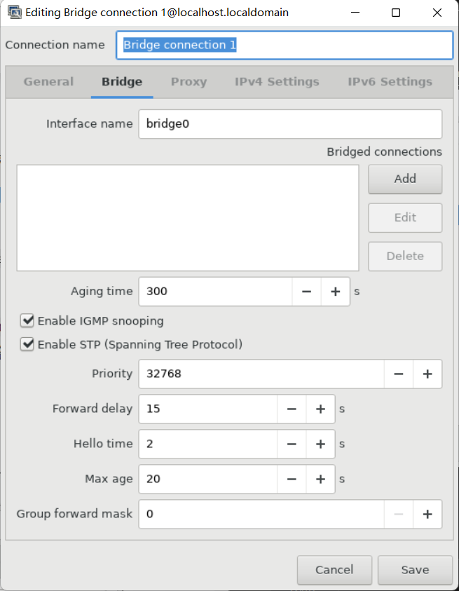
- Optional: Configure other bridge settings, such as Spanning Tree Protocol (STP) options.
- Configure the IP settings for the bridge. Skip this step if you want to use this bridge as a port for other devices.
- On the IPv4 Settings tab, configure the IPv4 settings. For example, to set a static IPv4 address, netmask, default gateway, DNS server, and DNS search domain:
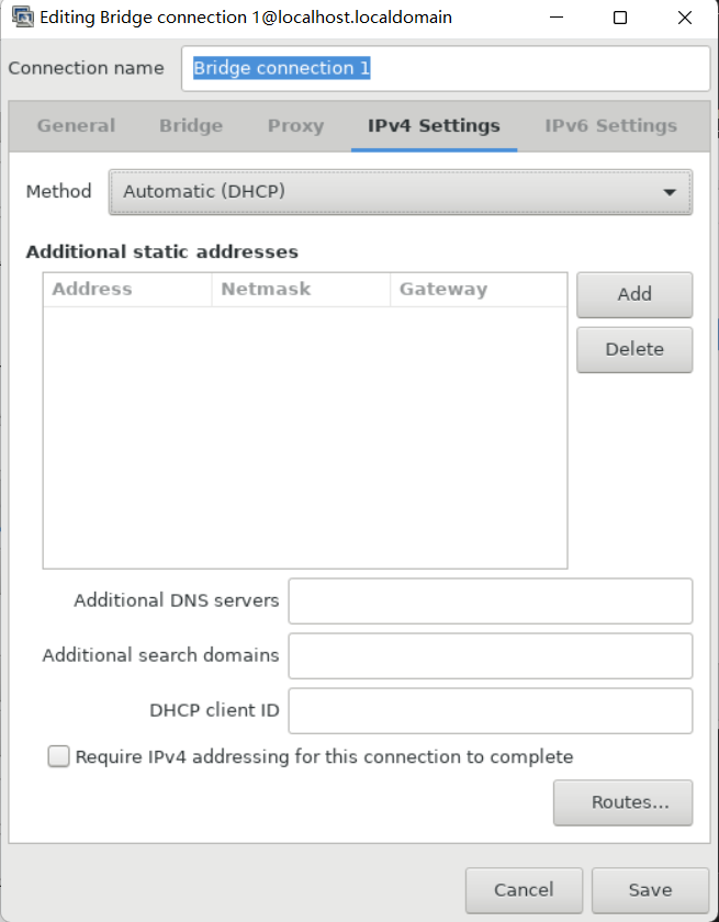
- On the IPv6 Settings tab, configure the IPv6 settings. For example, to set a static IPv6 address, netmask, default gateway, DNS server, and DNS search domain:
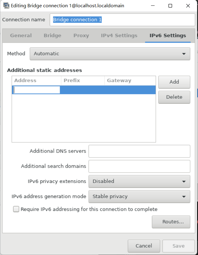
- Save the bridge connection.
- Close nm-connection-editor.
Verify
- Use the ip command to display the link status of the Ethernet device as a specific bridge port.
# ip link show master bridge0
3: enp7s0: <BROADCAST,MULTICAST,UP,LOWER_UP> mtu 1500 qdisc fq_codel master bridge0 state UP mode DEFAULT group default qlen 1000
    link/ether 52:54:00:62:61:0e brd ff:ff:ff:ff:ff:ff
4: enp8s0: <BROADCAST,MULTICAST,UP,LOWER_UP> mtu 1500 qdisc fq_codel master bridge0 state UP mode DEFAULT group default qlen 1000
    link/ether 52:54:00:9e:f1:ce brd ff:ff:ff:ff:ff:ff
# bridge link show
3: enp7s0: <BROADCAST,MULTICAST,UP,LOWER_UP> mtu 1500 master bridge0 state forwarding priority 32 cost 100
4: enp8s0: <BROADCAST,MULTICAST,UP,LOWER_UP> mtu 1500 master bridge0 state listening priority 32 cost 100
5: enp9s0: <BROADCAST,MULTICAST,UP,LOWER_UP> mtu 1500 master bridge1 state forwarding priority 32 cost 100
6: enp11s0: <BROADCAST,MULTICAST,UP,LOWER_UP> mtu 1500 master bridge1 state blocking priority 32 cost 100
...
To display the status of a specific Ethernet device, use the bridge link show dev ethernet_device_name command.
12.3. Use nmstatectl to configure network bridging
Prerequisites
- Install two or more physical or virtual network devices in the server.
- To use an Ethernet device as a port of a bridge, a physical or virtual Ethernet device must be installed in the server.
- To use a team, bond or VLAN device as a port in a bridge, set the interface name in the port list and define the corresponding interface.
- The nmstate package is installed.
Process
- Create a YAML file, ~/create-bridge.yml , with the following content:
---
interfaces:
- name: bridge0
type: linux-bridge
state: up
ipv4:
    enabled: true
    address:
    - ip: 192.0.2.1
    prefix-length: 24
    dhcp: false
ipv6:
    enabled: true
    address:
    - ip: 2001:db8:1::1
    prefix-length: 64
    autoconf: false
    dhcp: false
bridge:
    options:
    stp:
        enabled: true
    port:
    - name: enp1s0
    - name: enp7s0
- name: enp1s0
type: ethernet
state: up
- name: enp7s0
type: ethernet
state: up

routes:
config:
- destination: 0.0.0.0/0
    next-hop-address: 192.0.2.254
    next-hop-interface: bridge0
- destination: ::/0
    next-hop-address: 2001:db8:1::fffe
    next-hop-interface: bridge0
dns-resolver:
config:
    search:
    - example.com
    server:
    - 192.0.2.200
    - 2001:db8:1::ffbb
# nmstatectl apply ~/create-bridge.yml
Verify
- Display the status of the device and the connection:
# nmcli device status
DEVICE      TYPE      STATE      CONNECTION
bridge0     bridge    connected  bridge0
# nmcli connection show bridge0
connection.id:              bridge0
connection.uuid:            e2cc9206-75a2-4622-89cf-1252926060a9
connection.stable-id:       --
connection.type:            bridge
connection.interface-name:  bridge0
...
# nmstatectl show bridge0
第 13 章 配置网络团队(team)
13.1.网络团队简介
网络团队(network teaming)是一个合并或聚合网络接口的功能,它提供了一个高吞吐量或冗余的逻辑接口。
网络团队使用内核驱动程序来实现对数据包流、用户空间库以及用于其他任务的服务的快速处理。因此,网络团队是一个易扩展的解决方案,来满足负载均衡和冗余的要求。
13.2.了解控制器和端口接口的默认配置
在使用 NetworkManager 服务管理或排除团队或绑定端口接口故障时,请考虑以下默认配置:
- 启动控制器接口不会自动启动端口接口。
- 启动端口接口总会启动控制器接口。
- 停止控制器接口也会停止端口接口。
- 没有端口的控制器可以启动静态 IP 连接。
- 没有端口的控制器在启动 DHCP 连接时会等待端口。
- 当您添加带有载波的端口时,具有 DHCP 连接的控制器会等待端口完成。
- 当您添加不具有载波的端口时,具有 DHCP 连接的控制器继续等待端口。
13.3.网络团队和绑定功能的比较
网络团队和绑定功能的比较:
| 功能 | 网络绑定 | 网络团队 |
|---|---|---|
| 广播 Tx 策略 | 是 | 是 |
| 轮询 Tx 策略 | 是 | 是 |
| Active-backup Tx 策略 | 是 | 是 |
| LACP(802.3ad)支持 | 是(仅活动) | 是 |
| 基于 hash 的 Tx 策略 | 是 | 是 |
| 用户可以设置哈希功能 | 否 | 是 |
| TX 负载均衡支持(TLB) | 是 | 是 |
| LACP 哈希端口选择 | 是 | 是 |
| LACP 支持的负载均衡 | 否 | 是 |
| ethtool 链接监控 | 是 | 是 |
| ARP 链路监控 | 是 | 是 |
| NS/NA(IPv6)链路监控 | 否 | 是 |
| 端口启动/关闭延时 | 是 | 是 |
| 端口优先级和粘性("主要" 选项增强) | 否 | 是 |
| 独立的每个端口链路监控设置 | 否 | 是 |
| 多个链路监控设置 | 有限 | 是 |
| Lockless Tx/Rx 路径 | 否(rwlock) | 是(RCU) |
| VLAN 支持 | 是 | 是 |
| 用户空间运行时控制 | 有限 | 是 |
| 用户空间中的逻辑 | 否 | 是 |
| 可扩展性 | 难 | 易 |
| 模块化设计 | 否 | 是 |
| 性能开销 | 低 | 非常低 |
| D-Bus 接口 | 否 | 是 |
| 多设备堆栈 | 是 | 是 |
| 使用 LLDP 时零配置 | 否 | (计划中) |
| NetworkManager 支持 | 是 | 是 |
13.4.了解 teamd 服务、运行程序和 link-watchers
团队服务 teamd 团队驱动程序控制的一个实例。这个驱动的实例添加硬件设备驱动程序实例组成一个网络接口组。团队驱动程序向内核提供一个网络接口,如 team0。
teamd 服务对所有团队方法的实现提供通用的逻辑。这些功能对不同的负载共享和备份方法(如循环)是唯一的,并由称为 runners 的单独的代码单元来实现。管理员以 JavaScript 对象表示法(JSON)格式指定runners ,在创建实例时,JSON 代码被编译到 teamd 实例中。另外,在使用 NetworkManager 时,您可以在 team.runner 参数中设置 runner ,NetworkManager 会自动创建对应的 JSON 代码。
可用的 runner 如下:
- broadcast :转换所有端口上的数据。
- roundrobin :依次转换所有端口上的数据。
- activebackup :转换一个端口上的数据,而其他端口上的数据则作为备份保留。
- loadbalance:转换所有具有活跃的 Tx 负载均衡和基于 Berkeley 数据包过滤器(BPF)的 Tx 端口选择器的端口上的数据。
- random :转换随机选择的端口上的数据。
- lacp :实现 802.3ad 链路聚合控制协议(LACP)。
teamd 服务使用链路监视器来监控从属设备的状态。可用的 link-watchers 如下:
- ethtool :libteam 库使用 ethtool 工具来监视链接状态的变化。这是默认的 link-watcher。
- arp_ping: libteam 库使用 arp_ping 工具来监控使用地址解析协议(ARP)的远端硬件地址是否存在。
- nsna_ping: 在 IPv6 连接上,libteam 库使用来自 IPv6 邻居发现协议的邻居广告和邻居请求功能来监控邻居接口的存在。
每个 runner 都可以使用任何链接监视器,但 lacp 除外。此 runner 只能使用 ethtool 链接监视器。
13.5.安装 teamd 服务
要在 NetworkManager 中配置网络团队,您需要 NetworkManager 的 teamd 服务和团队插件。默认情况下,它们都安装在 OpenCloudOS 上。
# yum install teamd NetworkManager-team
13.6.使用 nmcli 命令配置网络团队
前提条件
- 在服务器中安装两个或者两个以上物理或者虚拟网络设备。
- 要将以太网设备用作团队的端口,必须在服务器中安装物理或者虚拟以太网设备并连接到交换机。
- 要将 bond、bridge 或 VLAN 设备用作团队的端口,您可以在创建团队时创建这些设备,或者预先创建它们。
流程
- 创建团队接口:
# nmcli connection add type team con-name team0 ifname team0 team.runner activebackup
此命令创建一个使用 activebackup runner、名为 team0 的网络团队。 2. 设置链接监视器。例如,要在 team0 连接配置文件中设置 ethtool 链接监视器:
# nmcli connection modify team0 team.link-watchers "name=ethtool"
链路监视器支持不同的参数。要为链路监视器设置参数,请在 name 属性中以空格分隔的方式来指定它们。请注意,name 属性必须用引号包围起来。例如,要使用 ethtool 链接监视器,并将其 delay-up 参数设置为 2500 毫秒(2.5 秒):
# nmcli connection modify team0 team.link-watchers "name=ethtool delay-up=2500"
要设置多个链路监视器,每个都使用特定的参数,不同的连接监视器以逗号分隔。以下示例使用 delay-up 参数设置 ethtool 链接监视器,使用 source-host 和 target-host 参数设置 arp_ping 链路监视器:
# nmcli connection modify team0 team.link-watchers "name=ethtool delay-up=2, name=arp_ping source-host=192.0.2.1 target-host=192.0.2.2"
# nmcli device status
DEVICE  TYPE      STATE         CONNECTION
enp7s0  ethernet  disconnected  --
enp8s0  ethernet  disconnected  --
bond0   bond      connected  bond0
bond1   bond      connected  bond1
...
在本例中:
- 没有配置 enp7s0 和 enp8s0 。要将这些设备用作端口,请在下一步中添加连接配置集。请注意,您只能在没有分配给任何连接的团队中使用以太网接口。
- bond0 和 bond1 已有连接配置文件。要将这些设备用作端口,请在下一步中修改其配置集。
-
为团队分配端口接口:
-
如果没有配置您要分配给团队的接口,为其创建新的连接配置集:
# nmcli connection add type ethernet slave-type team con-name team0-port1 ifname enp7s0 master team0
# nmcli connection add type ethernet slave-type team con-name team0-port2 ifname enp8s0 master team0
这些命令为 enp7s0 和 enp8s0 创建配置文件,并将它们添加到 team0 连接中。 2. 要现有的连接配置文件分配给团队,请将这些连接的 master 参数设为 team0 :
# nmcli connection modify bond0 master team0
# nmcli connection modify bond1 master team0
这些命令将名为 bond0 和 bond1 的现有连接配置文件分配给 team0 连接。 5. 配置团队的 IP 设置。如果要使用这个团队作为其它设备的端口,请跳过这一步。
-
配置 IPv4 设置。例如:要设置 team0 连接的静态 IPv4 地址、网络掩码、默认网关、DNS 服务器和 DNS 搜索域,请输入:
# nmcli connection modify team0 ipv4.addresses '192.0.2.1/24' # nmcli connection modify team0 ipv4.gateway '192.0.2.254' # nmcli connection modify team0 ipv4.dns '192.0.2.253' # nmcli connection modify team0 ipv4.dns-search 'example.com' # nmcli connection modify team0 ipv4.method manual - 配置 IPv6 设置。例如:要设置 team0 连接的静态 IPv6 地址、网络掩码、默认网关、DNS 服务器和 DNS 搜索域,请输入:
# nmcli connection modify team0 ipv6.addresses '2001:db8:1::1/64' # nmcli connection modify team0 ipv6.gateway '2001:db8:1::fffe' # nmcli connection modify team0 ipv6.dns '2001:db8:1::fffd' # nmcli connection modify team0 ipv6.dns-search 'example.com' # nmcli connection modify team0 ipv6.method manual - 激活连接:
# nmcli connection up team0
验证
- 显示团队状态:
# teamdctl team0 state
setup:
runner: activebackup
ports:
enp7s0
    link watches:
    link summary: up
    instance[link_watch_0]:
        name: ethtool
        link: up
        down count: 0
enp8s0
    link watches:
    link summary: up
    instance[link_watch_0]:
        name: ethtool
        link: up
        down count: 0
runner:
active port: enp7s0
在这个示例中,两个端口都是上线的。
13.7.使用 nm-connection-editor 配置网络团队
本节介绍了如何使用 nm-connection-editor 应用程序配置网络团队。
请注意:nm-connection-editor 只能向团队添加新端口。要使用现有的连接配置文件作为端口,请使用 nmcli 工具来创建团队,如 使用 nmcli 命令配置网络团队 中所述。
前提条件
- 在服务器中安装两个或者两个以上物理或者虚拟网络设备。
- 要将以太网设备用作团队的端口,必须在服务器中安装物理或者虚拟以太网设备。
- 要使用 team、bond 或 VLAN 设备作为团队的端口,请确保这些设备还没有配置。
流程
- 在终端输入 nm-connection-editor 。
- 点击 + 按钮来添加一个新的连接。
- 选择 Team 连接类型,然后单击 Create。
- 在 Team 选项卡中:
- 可选:在 Interface name 字段中设置团队接口的名称。
- 点击 Add 按钮为网络接口添加新连接配置集,并将配置集作为端口添加到团队。
- 选择接口的连接类型。例如,为有线连接选择 Ethernet。
- 可选:为端口设置连接名称。
- 如果您要为以太网设备创建一个连接配置文件,请打开 Ethernet 选项卡,然后在 Device 字段中选择您要作为端口添加到团队的网络接口。如果您选择了不同的设备类型,请相应地进行配置。请注意,您只能在没有分配给任何连接的团队中使用以太网接口。
- 点 Save。
- 对您要添加到团队的每个接口重复前面的步骤。
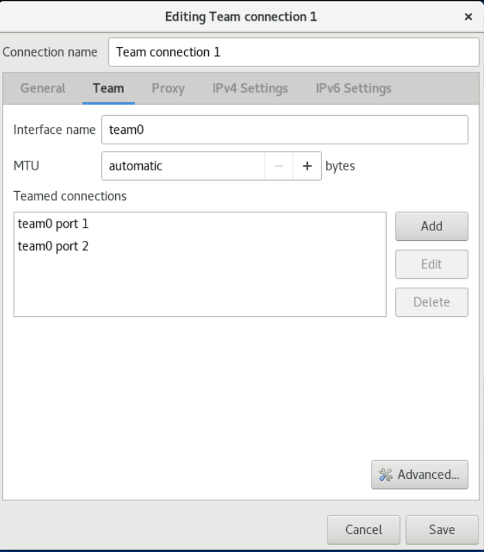
- 点 Advanced 按钮将高级选项设置为团队连接。
- 在 Runner 选项卡中,选择 runner。
- 在 Link Watcher 选项卡中,设置链接监视器及其可选设置。
- 点确定。
- 配置团队的 IP 设置。如果要使用这个团队作为其它设备的端口,请跳过这一步。
- 在 IPv4 Settings 选项卡中,配置 IPv4 设置。例如,设置静态 IPv4 地址、网络掩码、默认网关、DNS 服务器和 DNS 搜索域:
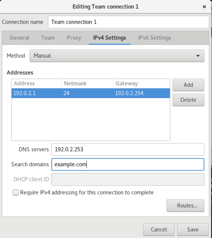
- 在 IPv6 Settings 选项卡中,配置 IPv6 设置。例如,设置静态 IPv6 地址、网络掩码、默认网关、DNS 服务器和 DNS 搜索域:
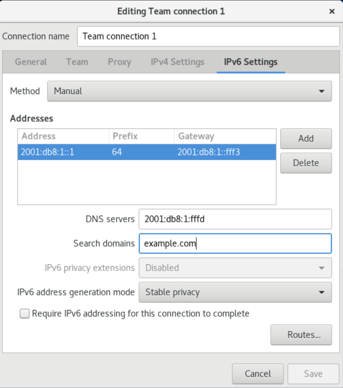
- 保存团队连接。
- 关闭 nm-connection-editor。
验证
- 显示团队状态:
# teamdctl team0 state
setup:
runner: activebackup
ports:
enp7s0
    link watches:
    link summary: up
    instance[link_watch_0]:
        name: ethtool
        link: up
        down count: 0
enp8s0
    link watches:
    link summary: up
    instance[link_watch_0]:
        name: ethtool
        link: up
        down count: 0
runner:
active port: enp7s0
第14章 配置网络绑定
14.1.网络绑定简介
网络绑定(network bonding)是组合或者整合网络接口的方法,以便提供一个高吞吐量或冗余的逻辑接口。
active-backup、balance-tlb 和 balance-alb 模式不需要网络交换机的任何具体配置。然而,其他绑定模式需要配置交换机来聚合链接。例如,对于模式 0、2 和 3,Cisco 交换机需要 EtherChannel ,但对于模式 4,需要链接聚合控制协议(LACP)和 EtherChannel。
14.2.控制器和端口接口的默认配置
在使用 NetworkManager 服务管理或排除团队或绑定端口接口故障时,请考虑以下默认配置:
- 启动控制器接口不会自动启动端口接口。
- 启动端口接口总会启动控制器接口。
- 停止控制器接口也会停止端口接口。
- 没有端口的控制器可以启动静态 IP 连接。
- 没有端口的控制器在启动 DHCP 连接时会等待端口。
- 当您添加带有载波的端口时,具有 DHCP 连接的控制器会等待端口完成。
- 当您添加不具有载波的端口时,具有 DHCP 连接的控制器继续等待端口。
14.3.网络团队和绑定功能的比较
网络团队和绑定功能的比较:
| 功能 | 网络绑定 | 网络团队 |
|---|---|---|
| 广播 Tx 策略 | 是 | 是 |
| 轮询 Tx 策略 | 是 | 是 |
| Active-backup Tx 策略 | 是 | 是 |
| LACP(802.3ad)支持 | 是(仅活动) | 是 |
| 基于 hash 的 Tx 策略 | 是 | 是 |
| 用户可以设置哈希功能 | 否 | 是 |
| TX 负载均衡支持(TLB) | 是 | 是 |
| LACP 哈希端口选择 | 是 | 是 |
| LACP 支持的负载均衡 | 否 | 是 |
| ethtool 链接监控 | 是 | 是 |
| ARP 链路监控 | 是 | 是 |
| NS/NA(IPv6)链路监控 | 否 | 是 |
| 端口启动/关闭延时 | 是 | 是 |
| 端口优先级和粘性("主要" 选项增强) | 否 | 是 |
| 独立的每个端口链路监控设置 | 否 | 是 |
| 多个链路监控设置 | 有限 | 是 |
| Lockless Tx/Rx 路径 | 否(rwlock) | 是(RCU) |
| VLAN 支持 | 是 | 是 |
| 用户空间运行时控制 | 有限 | 是 |
| 用户空间中的逻辑 | 否 | 是 |
| 可扩展性 | 难 | 易 |
| 模块化设计 | 否 | 是 |
| 性能开销 | 低 | 非常低 |
| D-Bus 接口 | 否 | 是 |
| 多设备堆栈 | 是 | 是 |
| 使用 LLDP 时零配置 | 否 | (计划中) |
| NetworkManager 支持 | 是 | 是 |
14.4.绑定模式对应上游交换机配置
下表描述了根据绑定模式,您必须对上游交换机应用哪些设置:
| 绑定模式 | 交换机上的配置 |
|---|---|
| 0 - balance-rr | 需要启用静态的 Etherchannel(未启用 LACP 协商) |
| 1 - active-backup | 需要可自主端口 |
| 2 - balance-xor | 需要启用静态的 Etherchannel(未启用 LACP 协商) |
| 3 - broadcast | 需要启用静态的 Etherchannel(未启用 LACP 协商) |
| 4 - 802.3ad | 需要启用 LACP 协商的 Etherchannel |
| 5 - balance-tlb | 需要可自主端口 |
| 6 - balance-alb | 需要可自主端口 |
有关在交换机中配置这些设置,请查看交换机文档。
14.5.使用 nmcli 命令配置网络绑定
前提条件
- 在服务器中安装两个或者两个以上物理或者虚拟网络设备。
- 要将以太网设备用作团队的端口,必须在服务器中安装物理或者虚拟以太网设备并连接到交换机。
- 要将 bond、bridge 或 VLAN 设备用作团队的端口,您可以在创建团队时创建这些设备,或者预先创建它们。
流程
- 创建绑定接口
# nmcli connection add type bond con-name bond0 ifname bond0 bond.options "mode=active-backup"
这个命令会创建一个使用 active-backup 模式、名为 bond0 的绑定。
要额外设置介质独立接口(MII)监控间隔,请在 bond.options 属性中添加 miimon=interval 选项。例如,要使用同样的命令,但还需要将 MII 监控间隔设为 1000 毫秒(1 秒),请输入:
# nmcli connection add type bond con-name bond0 ifname bond0 bond.options "mode=active-backup,miimon=1000"
# nmcli device status
DEVICE   TYPE      STATE         CONNECTION
enp7s0   ethernet  disconnected  --
enp8s0   ethernet  disconnected  --
bridge0  bridge    connected     bridge0
bridge1  bridge    connected     bridge1
...
在本例中:
- 没有配置 enp7s0 和 enp8s0 。要将这些设备用作端口,请在下一步中添加连接配置集。
- bridge0 和 bridge1 都有现有的连接配置文件。要将这些设备用作端口,请在下一步中修改其配置集。
-
为绑定分配接口
-
如果没有配置您要分配给绑定的接口,为其创建新的连接配置集:
# nmcli connection add type ethernet slave-type bond con-name bond0-port1 ifname enp7s0 master bond0
# nmcli connection add type ethernet slave-type bond con-name bond0-port2 ifname enp8s0 master bond0
这些命令为 enp7s0 和 enp8s0 创建配置文件,并将它们添加到 bond0 连接中。 2. 要将现有连接的配置文件分配给绑定,请将这些连接的 master 参数设为 bond0 :
# nmcli connection modify bridge0 master bond0
# nmcli connection modify bridge1 master bond0
这些命令将名为 bridge0 和 bridge1 的现有连接配置文件分配给 bond0 连接。 4. 配置绑定的 IP 设置。如果要使用这个绑定作为其它设备的端口,请跳过这一步。
-
配置 IPv4 设置。例如,要对 bond0 连接设置静态 IPv4 地址、网络掩码、默认网关、DNS 服务器和 DNS 搜索域设置,请输入:
# nmcli connection modify bond0 ipv4.addresses '192.0.2.1/24' # nmcli connection modify bond0 ipv4.gateway '192.0.2.254' # nmcli connection modify bond0 ipv4.dns '192.0.2.253' # nmcli connection modify bond0 ipv4.dns-search 'example.com' # nmcli connection modify bond0 ipv4.method manual - 配置 IPv6 设置。例如,要对 bond0 连接设置静态 IPv6 地址、网络掩码、默认网关、DNS 服务器和 DNS 搜索域设置,请输入:
# nmcli connection modify bond0 ipv6.addresses '2001:db8:1::1/64' # nmcli connection modify bond0 ipv6.gateway '2001:db8:1::fffe' # nmcli connection modify bond0 ipv6.dns '2001:db8:1::fffd' # nmcli connection modify bond0 ipv6.dns-search 'example.com' # nmcli connection modify bond0 ipv6.method manual - 激活连接:
# nmcli connection up bond0
# nmcli device
DEVICE   TYPE      STATE      CONNECTION
...
enp7s0   ethernet  connected  bond0-port1
enp8s0   ethernet  connected  bond0-port2
当您激活连接的任何端口时,NetworkManager 也激活绑定,但不会激活它的其它端口。您可以配置 OpenCloudOS ,在启用绑定时自动启用所有端口:
- 启用绑定连接的 connection.autoconnect-slaves 参数:
# nmcli connection modify bond0 connection.autoconnect-slaves 1 - 重新激活桥接:
# nmcli connection up bond0
验证
- 在主机中暂时拔掉网线。
请注意,无法使用软件工具正确测试链路失败事件。停用连接的工具(如 nmcli ),只显示绑定驱动程序可以处理端口配置的更改,而不是实际的链接失败事件。
- 显示绑定状态
# cat /proc/net/bonding/bond0
14.6.使用 nm-connection-editor 配置网络绑定
本节介绍了如何使用 nm-connection-editor 应用程序配置网络绑定。
请注意:nm-connection-editor 只能向绑定添加新端口。要使用现有连接配置文件作为端口,请使用 nmcli 工具创建绑定。
前提条件
- 在服务器中安装两个或者两个以上物理或者虚拟网络设备。
- 要将以太网设备用作绑定的端口,必须在服务器中安装物理或者虚拟以太网设备。
- 要使用 team、bond 或 VLAN 设备作为绑定的端口,请确保这些设备还没有配置
流程
- 在终端中输入 nm-connection-editor 。
- 点击 + 按钮来添加一个新的连接。
- 选择 Bond 连接类型,再单击 Create。
- 在 Bond 选项卡中:
- 可选:在 Interface name 字段中设置绑定接口的名称。
- 单击 Add 按钮,将网络接口作为端口添加到绑定中。
- 选择接口的连接类型。例如,为有线连接选择 Ethernet。
- 可选:为端口设置连接名称。
- 如果您要为以太网设备创建连接配置文件,请打开 Ethernet 选项卡,在 Device 字段中选择您要作为端口添加到绑定的网络接口。如果您选择了不同的设备类型,请相应地进行配置。请注意,您只能在没有配置的绑定中使用以太网接口。
- 点 Save。
- 对您要添加到绑定的每个接口重复前面的步骤:
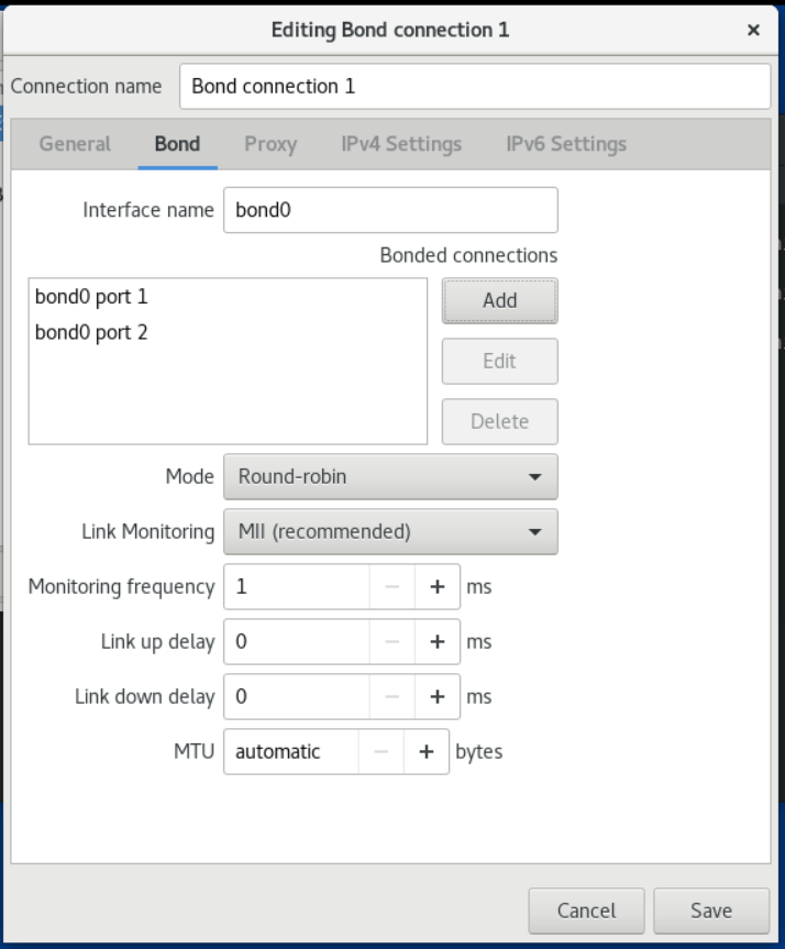
- 可选:设置其他选项,如介质独立接口(MII)监控间隔。
- 配置绑定的 IP 设置。如果要使用这个绑定作为其它设备的端口,请跳过这一步。
- 在 IPv4 Settings 选项卡中,配置 IPv4 设置。例如,设置静态 IPv4 地址、网络掩码、默认网关、DNS 服务器和 DNS 搜索域:
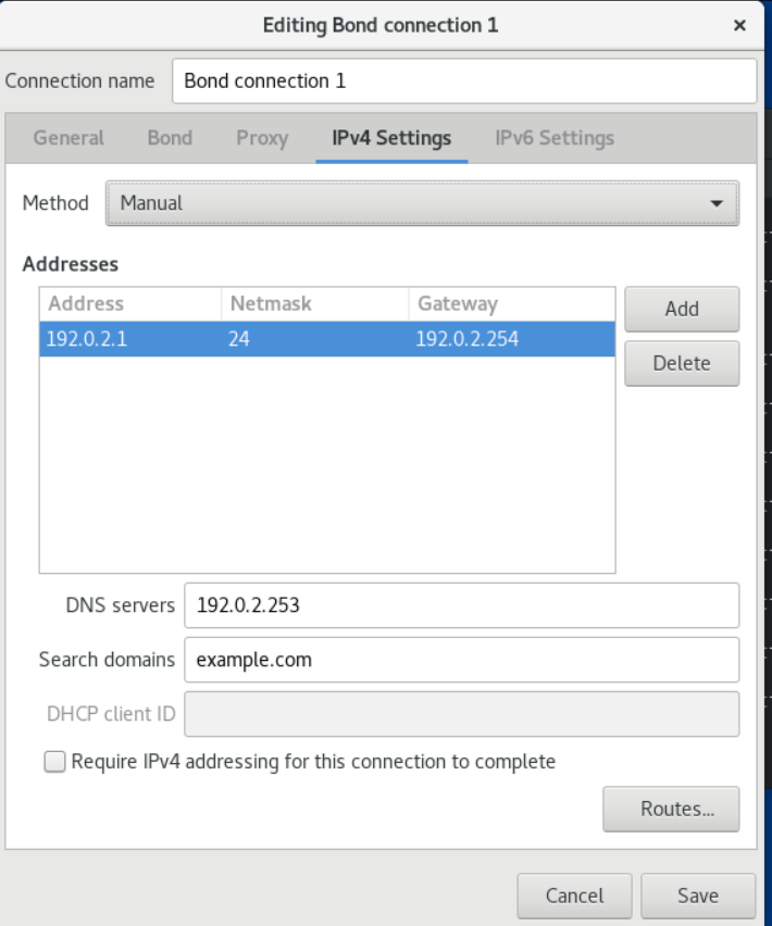
- 在 IPv6 Settings 选项卡中,配置 IPv6 设置。例如,设置静态 IPv6 地址、网络掩码、默认网关、DNS 服务器和 DNS 搜索域:
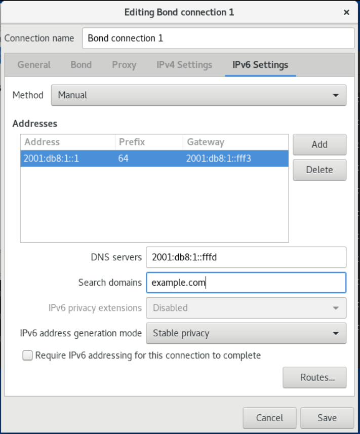
- 点 Save 保存绑定连接。
- 关闭 nm-connection-editor。
验证
- 在主机中暂时拔掉网线。
请注意,无法使用软件工具正确测试链路失败事件。停用连接的工具(如 nmcli ),只显示绑定驱动程序可以处理端口配置的更改,而不是实际的链接失败事件。
- 显示绑定状态
# cat /proc/net/bonding/bond0
14.7.使用 nmstatectl 配置网络绑定
前提条件
- 在服务器中安装两个或者两个以上物理或者虚拟网络设备。
- 要将以太网设备用作绑定中的端口,必须在服务器中安装物理或者虚拟以太网设备。
- 要在绑定中使用团队、网桥或 VLAN 设备作为端口,请在 port 列表中设置接口名称,并定义相应的接口。
- nmstate 软件包已安装。
流程
- 创建 ~/create-bond.yml YAML文件:
---
interfaces:
- name: bond0
type: bond
state: up
ipv4:
    enabled: true
    address:
    - ip: 192.0.2.1
    prefix-length: 24
    dhcp: false
ipv6:
    enabled: true
    address:
    - ip: 2001:db8:1::1
    prefix-length: 64
    autoconf: false
    dhcp: false
link-aggregation:
    mode: active-backup
    port:
    - enp1s0
    - enp7s0
- name: enp1s0
type: ethernet
state: up
- name: enp7s0
type: ethernet
state: up

routes:
config:
- destination: 0.0.0.0/0
    next-hop-address: 192.0.2.254
    next-hop-interface: bond0
- destination: ::/0
    next-hop-address: 2001:db8:1::fffe
    next-hop-interface: bond0

dns-resolver:
config:
    search:
    - example.com
    server:
    - 192.0.2.200
    - 2001:db8:1::ffbb
# nmstatectl apply /create-bond.yml
验证
- 显示设备和连接的状态:
# nmcli device status DEVICE TYPE STATE CONNECTION bond0 bond connected bond0 - 显示连接配置集的所有设置:
# nmcli connection show bond0 connection.id: bond0 connection.uuid: 79cbc3bd-302e-4b1f-ad89-f12533b818ee connection.stable-id: -- connection.type: bond connection.interface-name: bond0 ... - 以 YAML 格式显示连接设置:
# nmstatectl show bond0
14.8.使用 rhel-system-roles 软件配置网络绑定
前提条件
- ansible 和 rhel-system-roles 软件包已安装在控制节点上。
- 如果您在运行 playbook 时使用了非 root 用户,则要求此用户在受管节点上具有对应的 sudo 权限。
- 在服务器中安装两个或者两个以上物理或者虚拟网络设备。
流程
- 如果您用来执行 playbook 中指令的主机还没有被列入清单,则将主机 IP 或名称添加到 /etc/ansible/hosts Ansible 清单文件中:
node.example.com
---
- name: Configure a network bond that uses two Ethernet ports
hosts: node.example.com
become: true
tasks:
- include_role:
    name: rhel-system-roles.network

    vars:
    network_connections:
        # Define the bond profile
        - name: bond0
        type: bond
        interface_name: bond0
        ip:
            address:
            - "192.0.2.1/24"
            - "2001:db8:1::1/64"
            gateway4: 192.0.2.254
            gateway6: 2001:db8:1::fffe
            dns:
            - 192.0.2.200
            - 2001:db8:1::ffbb
            dns_search:
            - example.com
        bond:
            mode: active-backup
        state: up

        # Add an Ethernet profile to the bond
        - name: bond0-port1
        interface_name: enp7s0
        type: ethernet
        controller: bond0
        state: up

        # Add a second Ethernet profile to the bond
        - name: bond0-port2
        interface_name: enp8s0
        type: ethernet
        controller: bond0
        state: up
- 要以 root 用户身份连接到受管主机,请输入:
# ansible-playbook -u root ~/bond-ethernet.yml -
以用户身份连接到受管主机,请输入:
# ansible-playbook -u user_name --ask-become-pass ~/bond-ethernet.yml--ask-become-pass 选项确保 ansible-playbook 命令提示输入 -u user_name 选项中定义的用户的 sudo 密码。
如果没有指定 -u user_name 选项,ansible-playbook 以当前登录到控制节点的用户身份连接到受管主机。
14.9.创建网络绑定以便在不中断 VPN 的情况下在以太网和无线连接间进行切换
需要使用公司内网工作的用户通常会使用 VPN 访问远程资源。然而,如果工作主机在以太网和 Wi-Fi 连接间切换,例如:如果您是从带以太网连接的扩展坞中释放的笔记本电脑,VPN 连接就会中断。要避免这个问题,您可以在 active-backup 模式中创建使用以太网和 Wi-Fi 连接的网络绑定。
前提条件
- 主机包含以太网和 Wi-Fi 设备。
- 已创建以太网和 Wi-Fi 网络管理器连接配置集,且两个连接都可以独立工作。
- 此流程使用以下连接配置文件来创建名为 bond0 的网络绑定:
- 与 enp11s0u1 以太网设备关联的 Docking_station
- Wi-Fi 与 wlp1s0 Wi-Fi 设备关联
流程
- 在 active-backup 模式中创建一个绑定接口:
# nmcli connection add type bond con-name bond0 ifname bond0 bond.options "mode=active-backup"
这个命令将接口和连接配置文件命名为 bond0 。 2. 配置绑定的 IPv4 设置: - 如果您的网络中的 DHCP 服务器为主机分配 IPv4 地址,则不需要任何操作。 - 如果您的本地网络需要静态 IPv4 地址,请将地址、网络掩码、默认网关、DNS 服务器和 DNS 搜索域设为 bond0 连接:
# nmcli connection modify bond0 ipv4.addresses '192.0.2.1/24'
# nmcli connection modify bond0 ipv4.gateway '192.0.2.254'
# nmcli connection modify bond0 ipv4.dns '192.0.2.253'
# nmcli connection modify bond0 ipv4.dns-search 'example.com'
# nmcli connection modify bond0 ipv4.method manual
# nmcli connection modify bond0 ipv6.addresses '2001:db8:1::1/64'
# nmcli connection modify bond0 ipv6.gateway '2001:db8:1::fffe'
# nmcli connection modify bond0 ipv6.dns '2001:db8:1::fffd'
# nmcli connection modify bond0 ipv6.dns-search 'example.com'
# nmcli connection modify bond0 ipv6.method manual
# nmcli connection show
NAME             UUID                                  TYPE      DEVICE
Docking_station  256dd073-fecc-339d-91ae-9834a00407f9  ethernet  enp11s0u1
Wi-Fi            1f1531c7-8737-4c60-91af-2d21164417e8  wifi      wlp1s0
...
下一步需要连接配置集的名称和以太网设备名称。 5. 为绑定分配以太网连接的配置:
# nmcli connection modify Docking_station master bond0
# nmcli connection modify Wi-Fi master bond0
# nmcli connection modify bond0 +bond.options fail_over_mac=1
使用这个设置时,您必须将 Wi-Fi 设备的 MAC 地址设置为 allow 列表,而不是以太网和 Wi-Fi 设备的 MAC 地址。 8. 将与以太连接关联的设备设置为绑定的主设备:
# nmcli con modify bond0 +bond.options "primary=enp11s0u1"
# nmcli connection modify bond0 connection.autoconnect-slaves 1
# nmcli connection up bond0
验证
- 显示当前活跃的设备,绑定及其端口的状态:
# cat /proc/net/bonding/bond0
Ethernet Channel Bonding Driver: v3.7.1 (April 27, 2011)

Bonding Mode: fault-tolerance (active-backup) (fail_over_mac active)
Primary Slave: enp11s0u1 (primary_reselect always)
Currently Active Slave: enp11s0u1
MII Status: up
MII Polling Interval (ms): 1
Up Delay (ms): 0
Down Delay (ms): 0
Peer Notification Delay (ms): 0

Slave Interface: enp11s0u1
MII Status: up
Speed: 1000 Mbps
Duplex: full
Link Failure Count: 0
Permanent HW addr: 00:53:00:59:da:b7
Slave queue ID: 0

Slave Interface: wlp1s0
MII Status: up
Speed: Unknown
Duplex: Unknown
Link Failure Count: 2
Permanent HW addr: 00:53:00:b3:22:ba
Slave queue ID: 0
第15章 配置 VPN 连接
本章介绍了如何配置虚拟专用网络(VPN)连接。
VPN 是通过互联网连接到本地网络的一种方式。本章使用 Libreswan 作为创建 VPN 的方法。libreswan 通过 VPN 的用户空间 IPsec 实现。VPN 通过在中间网络(比如互联网)设置隧道,实现 LAN 和另一个远程 LAN 之间的通信。为了安全起见,VPN 隧道总是使用认证和加密。对于加密操作,Libreswan 使用 NSS 库。
15.1.使用 control-center 配置 VPN 连接
前提条件
- 已安装 NetworkManager-libreswan-gnome 软件。
流程
- 进入 Settings 。
- 选择左侧 Network 条目。
- 点击 VPN 右侧的 + 图标。
- 选择 VPN 。
-
选择 Identity 菜单条目来查看基本配置选项:
-
General : 网关-远程 VPN 网关的名称或 IP 地址。
- Authentication :类型
- IKEv2(Certificate)- 客户端通过证书进行身份验证。更安全(默认)。
- IKEv1(XAUTH) - 客户端通过用户名和密码或预共享密钥(PSK)进行身份验证。
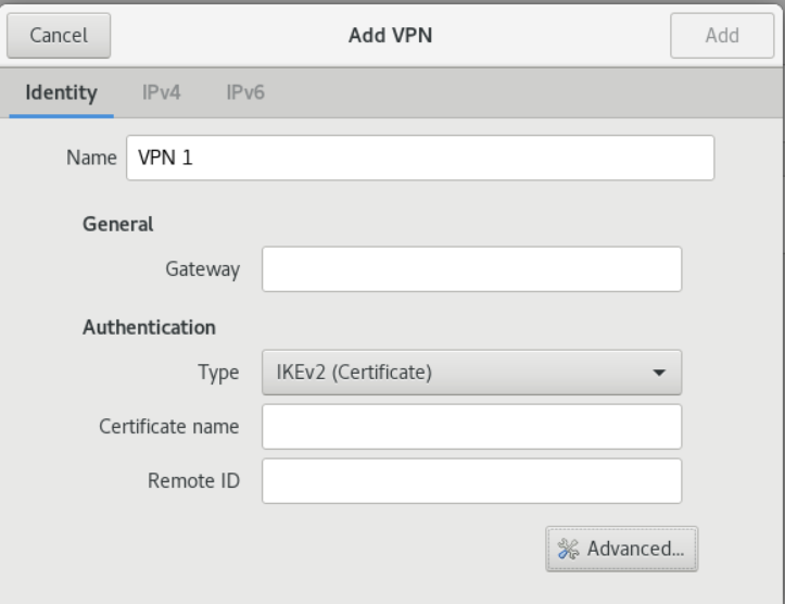 以下配置设置在 高级 部分中提供:
- Identification
- domain 如果需要,输入域名。
- Security
- phase1 Algorithms 对应 ike Libreswan 参数,输入用于身份验证和设置加密频道的算法。
- phase2 Algorithms 对应 esp Libreswan 参数,输入用于 IPsec 协商的算法。 检查 Disable PFS 字段以关闭 Perfect Forward Secrecy(PFS),以确保与不支持 PFS 的旧服务器兼容。
- Phase1 Lifetime 对应 ikelifetime Libreswan 参数,用于加密流量的密钥的有效期。
- phase2 Lifetime 对应 salifetime Libreswan 参数,在过期前特定连接实例应持续多长时间。 注意:为了安全起见,加密密钥应该不时地更改。
- Connectivity
- Remote Network 对应 rightsubnet Libreswan 参数,应该通过 VPN 访问的目标专用远程网络。
- Enable fragmentation 对应 fragmentation Libreswan 参数是否允许 IKE 碎片。有效值为 yes (默认)或 no。
- Enable Mobike 对应 mobike Libreswan 参数,是否允许移动性和多功能协议(MOBIKE、RFC 4555)启用连接以迁移其端点,而无需从头开始重新启动连接。这可用于在有线、无线或者移动数据连接之间进行切换的移动设备。值为 no (默认)或 yes。
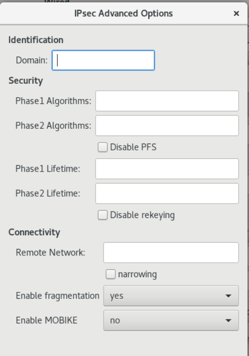
-
选择 IPv4 菜单条目:
-
IPv4 Method
- Automatic (DHCP) - 如果您要连接的网络使用 DHCP 服务器来分配动态 IP 地址,请选择此选项。
- 仅链接 - 如果您要连接的网络没有 DHCP 服务器且您不想手动分配 IP 地址,请选择这个选项。随机地址将根据 RFC 3927 分配前缀 169.254/16。
- Manual - 如果要手动分配 IP 地址,请选择这个选项。
- disable - 此连接禁用 IPv4。
- DNS:
当 Automatic 为 ON 时,将其切换到 OFF 以输入您要使用逗号分开的 DNS 服务器的 IP 地址。 - Routes
请注意,在 Routes 部分,当 Automatic 为 ON 时,会使用来自 DHCP 的路由,但您也可以添加其他静态路由。OFF 时,仅使用静态路由。
- Address 输入远程网络或主机的 IP 地址。
- Netmask 上面输入的 IP 地址 的子网掩码或前缀长度。
- Gateway 上面输入的 IP 地址 的子网掩码或前缀长度。
- Metric 网络成本,赋予此路由的首选值。数值越低,优先级越高。
- 仅将此连接用于其网络上的资源
选择这个复选框以防止连接成为默认路由。选择这个选项意味着只有特别用于路由的流量才会通过连接自动获得,或者手动输入到连接上。 7. 要在 VPN 连接中配置 IPv6 设置,请选择 IPv6 菜单条目:
-
IPv6 Method
- 自动 - 选择此选项以使用 IPv6 无状态地址自动配置(SLAAC),基于硬件地址和路由器公告(RA)创建自动无状态配置。
- 自动,仅 DHCP - 选择此选项以不使用 RA,而是直接从 DHCPv6 请求信息以创建有状态配置。
- 仅链接 - 如果您要连接的网络没有 DHCP 服务器且您不想手动分配 IP 地址,请选择这个选项。随机地址将根据 RFC 4862 进行分配,前缀为 FE80::0。
- Manual - 如果要手动分配 IP 地址,请选择这个选项。
- disable - 此连接禁用 IPv6。
请注意,DNS、Route s、仅将此连接用于其网络上的资源 对 IPv4 设置很常见。 8. 编辑完 VPN 连接后,点 Add 按钮自定义配置,或者使用 Apply 按钮为现有配置保存它。 9. 将配置集切换为 ON 激活 VPN 连接。
15.2.使用 nm-connection-editor 配置 VPN 连接
前提条件
- 已安装 NetworkManager-libreswan-gnome 软件包。
- 如果您配置了互联网密钥交换(IKEv2)验证:
- 将证书导入到IPsec网络安全服务(NSS)数据库中。
- NSS 数据库中的证书名称是已知的。
流程
- 在终端输入:nm-connection-editor
- 点击 + 按钮来添加一个新的连接。
- 选择 IPsec based VPN 连接类型,然后点击 Create。
-
在 VPN 选项卡中:
-
在 Gateway 字段中输入 VPN 网关的主机名或 IP 地址,然后选择验证类型。根据验证类型,您必须输入不同的额外信息:
-
IKEv2(Certificate)- 客户端通过证书进行身份验证,更安全。此设置需要在IPsec NSS 数据库中指定证书的名称。
-
IKEv1(XAUTH) - 客户端通过用户名和密码或预共享密钥(PSK)进行身份验证。此设置要求您输入以下信息:
- 用户名
- 密码
- 组名称
- 密钥
-
如果远程服务器为 IKE 交换指定了本地标识符,在 Remote ID 字段中输入准确的字符串。在运行 Libreswan 的远程服务器中,这个值是在服务器的 leftid 参数中设置的。
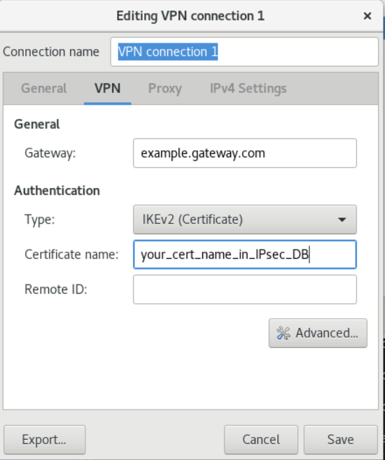
- (可选)点击 Advanced 按钮配置附加设置。您可以配置以下设置:
- Identification
- domain 如果需要,输入域名。
- Security
- phase1 Algorithms 对应 ike Libreswan 参数,输入用于身份验证和设置加密频道的算法。
- phase2 Algorithms 对应 esp Libreswan 参数,输入用于 IPsec 协商的算法。 检查 Disable PFS 字段以关闭 Perfect Forward Secrecy(PFS),以确保与不支持 PFS 的旧服务器兼容。
- Phase1 Lifetime 对应 ikelifetime Libreswan 参数,用于加密流量的密钥的有效期。
- phase2 Lifetime 对应 salifetime Libreswan 参数,在过期前特定连接实例应持续多长时间。 注意:为了安全起见,加密密钥应该不时地更改。
- Connectivity
- Remote Network 对应 rightsubnet Libreswan 参数,应该通过 VPN 访问的目标专用远程网络。
- Enable fragmentation 对应 fragmentation Libreswan 参数是否允许 IKE 碎片。有效值为 yes (默认)或 no。
- Enable Mobike 对应 mobike Libreswan 参数,是否允许移动性和多功能协议(MOBIKE、RFC 4555)启用连接以迁移其端点,而无需从头开始重新启动连接。这可用于在有线、无线或者移动数据连接之间进行切换的移动设备。值为 no (默认)或 yes。
- Identification
- 在 IPv4 Settings 选项卡中,选择 IP 分配方法,并可选择设置静态地址、DNS 服务器、搜索域和路由。
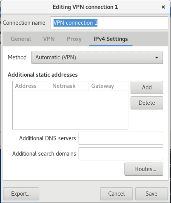
- 保存设置。
- 关闭 nm-connection-editor。
15.3.配置自动检测和使用 ESP 硬件卸载来加速 IPsec 连接
卸载硬件的封装安全负载(ESP)来加速以太网上的 IPsec 连接。默认情况下,Libreswan 会检测硬件是否支持这个功能,并默认启用 ESP 硬件卸载。本节描述了如何在禁用或显式启用此功能时启用自动检测。
前提条件
- 网卡支持 ESP 硬件卸载。
- 网络驱动程序支持 ESP 硬件卸载。
- IPsec 连接已配置且可以正常工作。
流程
- 编辑 VPN 连接的 /etc/ipsec.d/ 目录中的 Libreswan 配置文件,该文件应使用 ESP 硬件卸载支持的自动检测。
- 确保连接的设置中没有设置 nic-offload 参数。
- 如果您删除了 nic-offload,请重启 ipsec 服务:
# systemctl restart ipsec
验证
如果网卡支持 ESP 硬件卸载支持,请按照以下步骤验证结果:
- 显示 IPsec 连接使用的以太网设备计数器 tx_ipsec 和 rx_ipsec :
# ethtool -S enp1s0 | egrep "_ipsec" tx_ipsec: 10 rx_ipsec: 10 - 通过 IPsec 隧道发送流量。例如,ping 远程 IP 地址:
# ping -c 5 remote_ip_address - 再次显示 tx_ipsec 和 rx_ipsec 以太网设备计数器:
# ethtool -S enp1s0 | egrep "_ipsec"
    tx_ipsec: 15
    rx_ipsec: 15
如果计数器值增加了,说明 ESP 硬件卸载正常工作。
15.4.在绑定中配置 ESP 硬件卸载以加快 IPsec 连接
将封装安全负载(ESP)从硬件卸载可加速 IPsec 连接。如果出于故障转移原因而使用网络绑定,配置 ESP 硬件卸载的要求和流程与使用常规以太网设备的要求和流程不同。例如,在这种情况下,您可以对绑定启用卸载支持,内核会将设置应用到绑定的端口。
前提条件
- 绑定中的所有网卡都支持 ESP 硬件卸载。
- 网络驱动程序支持对绑定设备的 ESP 硬件卸载。在 RHEL 中,只有 ixgbe 驱动程序支持此功能。
- 绑定已配置且可以正常工作。
- 该绑定使用 active-backup 模式。绑定驱动程序不支持此功能的任何其他模式。
- IPsec 连接已配置且可以正常工作。
流程
- 对网络绑定启用 ESP 硬件卸载支持:
# nmcli connection modify bond0 ethtool.feature-esp-hw-offload on - 重新激活 bond0 连接:
# nmcli connection up bond0 - 编辑应使用 ESP 硬件卸载的连接的 /etc/ipsec.d/ 目录中的 Libreswan 配置文件,并将 nic-offload=yes 语句附加到连接条目:
conn example ... nic-offload=yes - 重启 ipsec 服务:
# systemctl restart ipsec
验证
- 显示绑定的活动端口:
# grep "Currently Active Slave" /proc/net/bonding/bond0 Currently Active Slave: enp1s0 - 显示 IPsec 连接使用的以太网设备计数器 tx_ipsec 和 rx_ipsec :
# ethtool -S enp1s0 | egrep "_ipsec" tx_ipsec: 10 rx_ipsec: 10 - 通过 IPsec 隧道发送流量。例如,ping 远程 IP 地址:
# ping -c 5 remote_ip_address - 再次显示 tx_ipsec 和 rx_ipsec 以太网设备计数器:
# ethtool -S enp1s0 | egrep "_ipsec"
    tx_ipsec: 15
    rx_ipsec: 15
如果计数器值增加了,说明 ESP 硬件卸载正常工作。
第16章 配置 IP 隧道
与 VPN 类似,IP 隧道通过第三方网络(如互联网)直接连接两个子网络。但是不是所有的隧道协议都支持加密。
建立隧道网络的路由器至少需要两个接口:
- 一个连接到本地网络的接口
- 一个连接到建立隧道的网络的接口。
要建立隧道,您可以在两个路由器中使用来自远程子网的 IP 地址创建一个虚拟接口。
NetworkManager 支持以下 IP 隧道:
- 通用路由封装(GRE)
- IPv6 上的通用路由封装(IP6GRE)
- 通用路由封装终端接入点(GRETAP)
- 通用路由登录在 IPv6(IP6GRETAP)上
- IPv4 over IPv4(IPIP)
- IPv4 over IPv6(IPIP6)
- IPv6 over IPv6(IP6IP6)
- 简单的互联网转换(SIT)
根据类型,这些通道在 Open Systems Interconnection(OSI)模型的第 2 层或 3 层动作。
16.1.使用 nmcli 配置 IPIP 隧道
IP over IP(IPIP)隧道工作在 OSI 模型第 3 层,通过 IPIP 隧道发送的数据没有加密。出于安全考虑,应只在已经加密的数据中使用隧道,比如 HTTPS。
请注意,IPIP 隧道只支持单播数据包。如果您需要支持多播的 IPv4 隧道,请参阅 使用 nmcli 配置 GRE 隧道来封装 IPv4 数据包中的第 3 层流量。
下图描述了如何在两个路由器之间创建 IPIP 隧道以通过互联网连接两个内部子网,如下图所示:
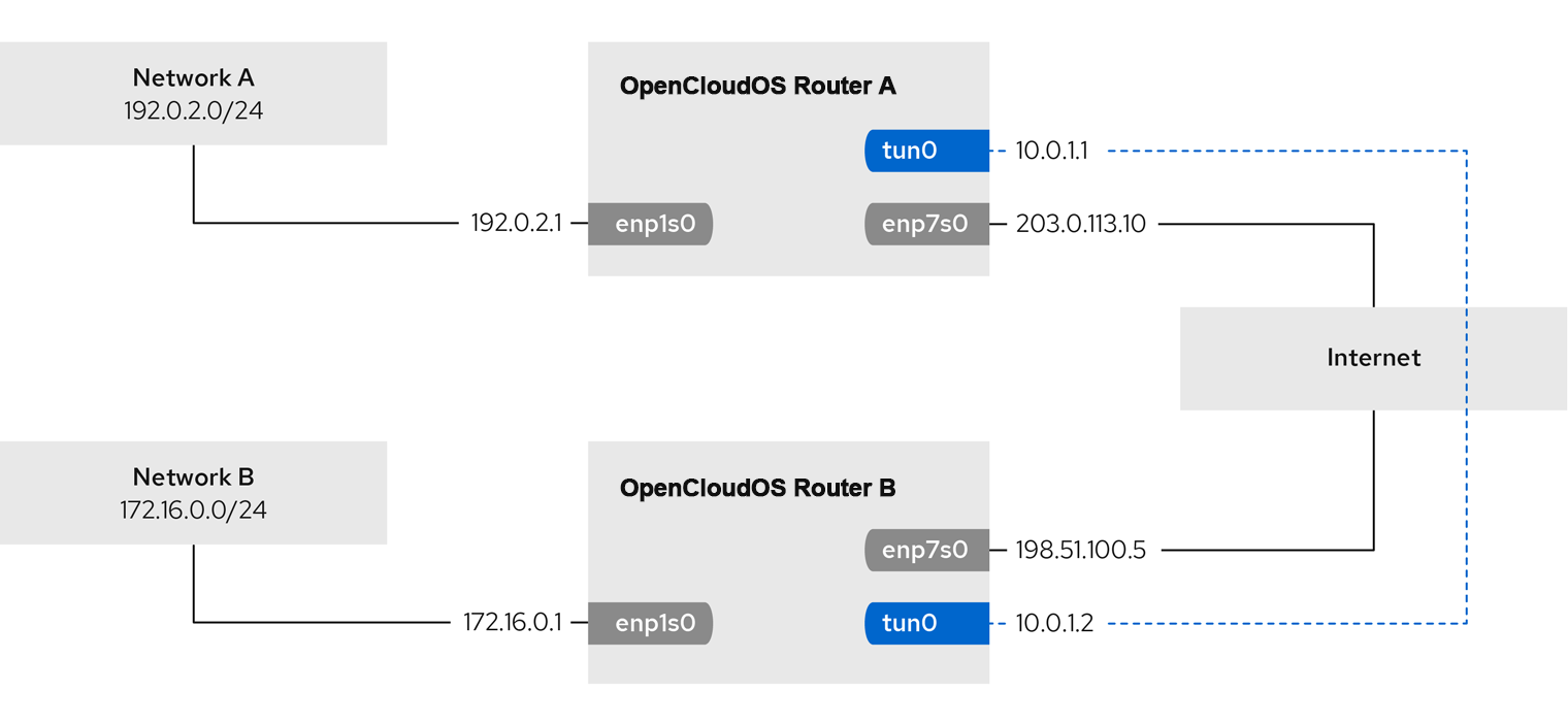
前提条件
- 每个路由器都有一个网络接口,它连接到其本地子网。
- 每个路由器都有一个网络接口,它连接到互联网。
- 您需要通过隧道发送的流量是 IPv4 单播。
流程
- 在网络 A 的路由器上:
-
创建名为 tun0 的 IPIP 隧道接口:
# nmcli connection add type ip-tunnel ip-tunnel.mode ipip con-name tun0 ifname tun0 remote 198.51.100.5 local 203.0.113.10remote 和 local 参数设置远程和本地路由器的公共 IP 地址。 2. 将 IPv4 地址设为 tun0 设备:
# nmcli connection modify tun0 ipv4.addresses '10.0.1.1/30'请注意,具有两个可用 IP 地址的 /30 子网足以满足隧道的需要。 3. 将 tun0 连接配置为使用手动 IPv4 配置:
4. 添加一个静态路由,其将到 172.16.0.0/24 网络的流量路由到路由器 B 上的隧道 IP:# nmcli connection modify tun0 ipv4.method manual5. 启用 tun0 连接。# nmcli connection modify tun0 +ipv4.routes "172.16.0.0/24 10.0.1.2"6. 启用数据包转发:# nmcli connection up tun02. 在网络 B 的路由器中: 1. 创建名为 tun0 的 IPIP 隧道接口:# echo "net.ipv4.ip_forward=1" > /etc/sysctl.d/95-IPv4-forwarding.conf # sysctl -p /etc/sysctl.d/95-IPv4-forwarding.conf# nmcli connection add type ip-tunnel ip-tunnel.mode ipip con-name tun0 ifname tun0 remote 203.0.113.10 local 198.51.100.5remote 和 local 参数设置远程和本地路由器的公共 IP 地址。 2. 将 IPv4 地址设为 tun0 设备:
3. 将 tun0 连接配置为使用手动 IPv4 配置:# nmcli connection modify tun0 ipv4.addresses '10.0.1.2/30'4. 添加一个静态路由,其将到 192.0.2.0/24 网络的流量路由到路由器 A 上的隧道 IP:# nmcli connection modify tun0 ipv4.method manual5. 启用 tun0 连接。# nmcli connection modify tun0 +ipv4.routes "192.0.2.0/24 10.0.1.1"6. 启用数据包转发:# nmcli connection up tun0# echo "net.ipv4.ip_forward=1" > /etc/sysctl.d/95-IPv4-forwarding.conf # sysctl -p /etc/sysctl.d/95-IPv4-forwarding.conf
验证
- 从每个路由器中,ping 路由器的内部接口的 IP 地址:
- 在路由器 A 上,ping 172.16.0.1 :
# ping 172.16.0.1 - 在路由器 A 上,ping 172.16.0.1 :
# ping 192.0.2.1
16.2. 使用 nmcli 配置 GRE 隧道来封装 IPv4 数据包中的第 3 层流量
Generic Routing Encapsulation(GRE)隧道封装 IPv4 数据包中的第 3 层流量,如 RFC 2784 所述。GRE 隧道可以使用有效的以太网类型封装任何第 3 层协议。通过 GRE 隧道发送的数据没有加密。出于安全考虑,应只在已经加密的数据中使用隧道,比如 HTTPS。
下图描述了如何在两个路由器之间创建 GRE 隧道以及通过互联网连接两个内部子网:
 注意, gre0 是保留词,请使用 gre1 为隧道命名。
前提条件
- 每个路由器都有一个网络接口,它连接到其本地子网。
- 每个路由器都有一个网络接口,它连接到互联网。
流程
- 在网络 A 的路由器上:
-
创建名为 gre1 的 GRE 隧道接口:
# nmcli connection add type ip-tunnel ip-tunnel.mode gre con-name gre1 ifname gre1 remote 198.51.100.5 local 203.0.113.10remote 和 local 参数设置远程和本地路由器的公共 IP 地址。 2. 将 IPv4 地址设为 gre1 设备:
# nmcli connection modify gre1 ipv4.addresses '10.0.1.1/30'请注意,具有两个可用 IP 地址的 /30 子网足以满足隧道的需要。 3. 将 gre1 连接配置为使用手动 IPv4 配置:
4. 添加一个静态路由,其将到 172.16.0.0/24 网络的流量路由到路由器 B 上的隧道 IP:# nmcli connection modify gre1 ipv4.method manual5. 启用 gre1 连接。# nmcli connection modify gre1 +ipv4.routes "172.16.0.0/24 10.0.1.2"6. 启用数据包转发:# nmcli connection up gre12. 在网络 B 的路由器中: 1. 创建名为 gre1 的 IPIP 隧道接口:# echo "net.ipv4.ip_forward=1" > /etc/sysctl.d/95-IPv4-forwarding.conf # sysctl -p /etc/sysctl.d/95-IPv4-forwarding.conf# nmcli connection add type ip-tunnel ip-tunnel.mode ipip con-name gre1 ifname gre1 remote 203.0.113.10 local 198.51.100.5remote 和 local 参数设置远程和本地路由器的公共 IP 地址。 2. 将 IPv4 地址设为 gre1 设备:
3. 将 gre1 连接配置为使用手动 IPv4 配置:# nmcli connection modify gre1 ipv4.addresses '10.0.1.2/30'4. 添加一个静态路由,其将到 192.0.2.0/24 网络的流量路由到路由器 A 上的隧道 IP:# nmcli connection modify gre1 ipv4.method manual5. 启用 gre1 连接。# nmcli connection modify gre1 +ipv4.routes "192.0.2.0/24 10.0.1.1"6. 启用数据包转发:# nmcli connection up gre1# echo "net.ipv4.ip_forward=1" > /etc/sysctl.d/95-IPv4-forwarding.conf # sysctl -p /etc/sysctl.d/95-IPv4-forwarding.conf
验证
- 从每个路由器中,ping 路由器的内部接口的 IP 地址:
- 在路由器 A 上,ping 172.16.0.1 :
# ping 172.16.0.1 - 在路由器 A 上,ping 172.16.0.1 :
# ping 192.0.2.1
16.3.配置 GRETAP 隧道来通过 IPv4 传输以太网帧
通用路由封装终端接入点(GRETAP)隧道在 OSI 模型第 2 层上运行,并封装 IPv4 数据包中的以太网流量,如 RFC 2784 所述。通过 GRETAP 隧道发送的数据没有加密。出于安全考虑,请通过 VPN 或不同的加密连接建立隧道。
下图描述了如何在两个路由器之间创建 GRETAP 隧道以使用桥接连接两个网络:
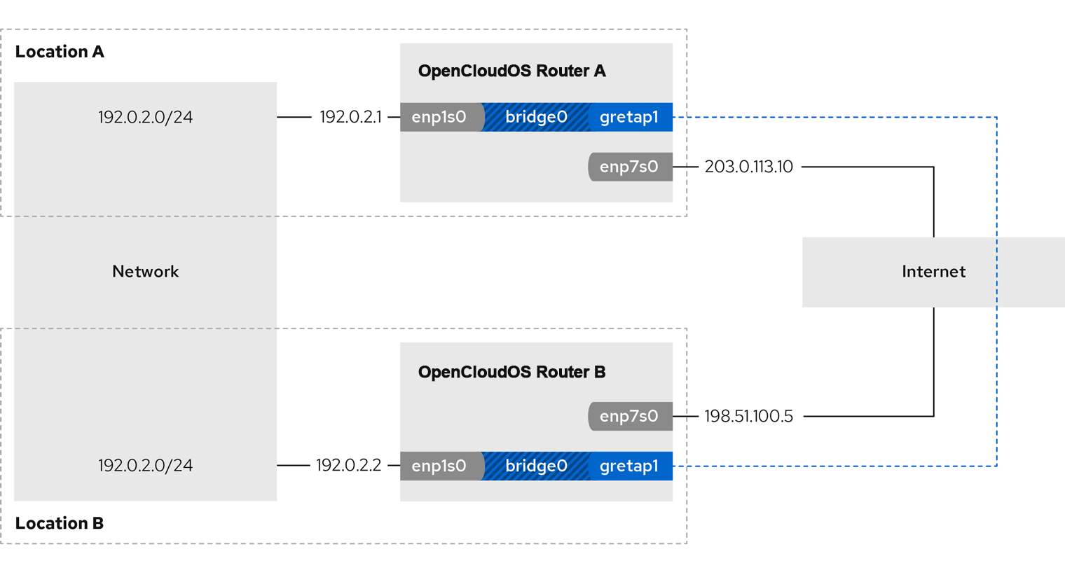 请注意,gretap0 是保留次,此处使用 gretap1 作为连接名称
前提条件
- 每个路由器都有一个网络接口,它连接到其本地网络,接口没有分配 IP 配置。
- 每个路由器都有一个网络接口,它连接到互联网。
流程
- 在网络 A 的路由器上:
- 创建名为 bridge0 的网桥接口:
# nmcli connection add type bridge con-name bridge0 ifname bridge0 - 配置网桥的 IP 设置:
# nmcli connection modify bridge0 ipv4.addresses '192.0.2.1/24' # nmcli connection modify bridge0 ipv4.method manual - 为连接到本地网络的接口添加新连接配置集到网桥:
# nmcli connection add type ethernet slave-type bridge con-name bridge0-port1 ifname enp1s0 master bridge0 -
为网桥添加 GRETAP 隧道接口的新连接配置集:
# nmcli connection add type ip-tunnel ip-tunnel.mode gretap slave-type bridge con-name bridge0-port2 ifname gretap1 remote 198.51.100.5 local 203.0.113.10 master bridge0remote 和 local 参数设置远程和本地路由器的公共 IP 地址。 5. 关闭 STP(Spanning Tree Protocol)如果您不需要:
6. 配置激活 bridge0 连接会自动激活网桥端口:# nmcli connection modify bridge0 bridge.stp no7. 激活 bridge0 连接:# nmcli connection modify bridge0 connection.autoconnect-slaves 12. 在网络 B 的路由器上: 1. 创建名为 bridge0 的网桥接口:# nmcli connection up bridge02. 配置网桥的 IP 设置:# nmcli connection add type bridge con-name bridge0 ifname bridge03. 为连接到本地网络的接口添加新连接配置集到网桥:# nmcli connection modify bridge0 ipv4.addresses '192.0.2.2/24' # nmcli connection modify bridge0 ipv4.method manual4. 为网桥添加 GRETAP 隧道接口的新连接配置集:# nmcli connection add type ethernet slave-type bridge con-name bridge0-port1 ifname enp1s0 master bridge0# nmcli connection add type ip-tunnel ip-tunnel.mode gretap slave-type bridge con-name bridge0-port2 ifname gretap1 remote 203.0.113.10 local 198.51.100.5 master bridge0remote 和 local 参数设置远程和本地路由器的公共 IP 地址。 5. 关闭 STP(Spanning Tree Protocol)如果您不需要:
6. 配置激活 bridge0 连接会自动激活网桥端口:# nmcli connection modify bridge0 bridge.stp no7. 激活 bridge0 连接:# nmcli connection modify bridge0 connection.autoconnect-slaves 1# nmcli connection up bridge0
验证
- 在两个路由器上,验证 enp1s0 和 gretap1 连接是否已连接,并且 CONNECTION 列是否显示端口的连接名称:
# nmcli device nmcli device DEVICE TYPE STATE CONNECTION ... bridge0 bridge connected bridge0 enp1s0 ethernet connected bridge0-port1 gretap1 iptunnel connected bridge0-port2 - 在每个路由器中,ping 路由器的内部接口的 IP 地址:
- 在路由器 A 上,ping 192.0.2.2 :
# ping 192.0.2.2 - 在路由器 B 上,ping 192.0.2.1 :
# ping 192.0.2.1
第17章 使用network-scripts
默认情况下,OpenCloudOS 使用 NetworkManager 配置和管理网络连接,/usr/sbin/ifup 和 /usr/sbin/ifdown 两个脚本使用 NetworkManager 来处理 /etc/sysconfig/network-scripts/ 目录中的 ifcfg 文件。
如果您需要使用 network-scripts 来配置和管理网络,您可以安装它。此时,/usr/sbin/ifup 和 /usr/sbin/ifdown 脚本会链接到管理网络配置的 shell 脚本。
- 安装 network-scripts 软件包:
# yum install network-scripts
第18章 端口镜像
网络管理员可以使用端口镜像复制从一个网络设备传输到另一个网络设备的入站和出站网络流量。使用端口镜像来监控、收集网络流量,可用于:
- 调试网络问题并调整网络流
- 检查并分析网络流量,来对网络问题进行故障排除
- 检测入侵
18.1.使用 nmcli 配置网络端口镜像
您可以使用 NetworkManager 配置端口镜像。以下流程通过将流量控制(tc)规则和过滤器添加到 enp1s0,将网络流量从 enp1s0 复制到 enp7s0 网络接口。
前提条件
- 有一个用作网络流量镜像的网络接口
流程
- 添加您要复制网络流量的网络连接配置集:
# nmcli connection add type ethernet ifname enp1s0 con-name enp1s0 autoconnect no - 将 prio qdisc 以 10:handle模式附加到流量出口 enp1s0 :
# nmcli connection modify enp1s0 +tc.qdisc "root prio handle 10:"
在没有子项的情况下,附加 prio qdisc 允许附加过滤器。 3. 为入口流量添加 qdisc,使用 ffff: handle 添加 qdisc:
# nmcli connection modify enp1s0 +tc.qdisc "ingress handle ffff:"
# nmcli connection modify enp1s0 +tc.tfilter "parent ffff: matchall action mirred egress mirror dev enp7s0"
# nmcli connection modify enp1s0 +tc.tfilter "parent 10: matchall action mirred egress mirror dev enp7s0"
matchall 过滤器与所有数据包匹配,mirred 操作会将数据包重定向到目的地。 5. 激活连接:
# nmcli connection up enp1s0
验证
- 安装 tcpdump 工具:
# yum install tcpdump - 查看目标设备上镜像的流量(enp7s0):
# tcpdump -i enp7s0
Chapter 19 Configuring Network Devices to Receive Traffic from All MAC Addresses (Promiscuous Mode)
Network devices typically intercept and read the packets that programs need to receive. You can configure network devices to accept traffic from all MAC addresses at the virtual switch or port group level.
Use this setting to:
- Diagnose network connection problems,
- Monitor network activity for increased security,
- Intercept private data in transit or intrusions in the network.
This chapter describes how to use the iproute2, nmcli, or nmstatectl tools to configure a network device to accept traffic from all MAC addresses. You can enable this mode for any type of network device except InfiniBand.
19.1. Use iproute2 to temporarily configure NIC promiscuous mode
This section describes configuring network devices to accept all traffic regardless of MAC address. Any changes made using the iproute2 tool are temporary and lost after a machine reboot.
Procedure
- Optional: Display the network interfaces to determine which interface you want to receive all traffic on:
# ip a 1: enp1s0: <NO-CARRIER,BROADCAST,MULTICAST,UP> mtu 1500 qdisc fq_codel state DOWN group default qlen 1000 link/ether 98:fa:9b:a4:34:09 brd ff:ff:ff:ff:ff:ff 2: bond0: <NO-CARRIER,BROADCAST,MULTICAST,MASTER,UP> mtu 1500 qdisc noqueue state DOWN group default qlen 1000 link/ether 6a:fd:16:b0:83:5c brd ff:ff:ff:ff:ff:ff 3: wlp1s0: <BROADCAST,MULTICAST,UP,LOWER_UP> mtu 1500 qdisc noqueue state UP group default qlen 1000 ... - Modify the device to enable or disable the accept-all-mac-addresses attribute.
- Enable accept-all-mac-addresses mode for enp1s0:
# ip link set enp1s0 promisc on - Disable accept-all-mac-addresses mode for enp1s0:
# ip link set enp1s0 promisc off
Verification
- Verify that the accept-all-mac-addresses mode is enabled:
# ip link show enp1s0 1: enp1s0: <NO-CARRIER,BROADCAST,MULTICAST,PROMISC,UP> mtu 1500 qdisc fq_codel state DOWN mode DEFAULT group default qlen 1000 link/ether 98:fa:9b:a4:34:09 brd ff:ff:ff:ff:ff:ff
The PROMISC flag in the device description indicates that the mode is enabled.
19.2. Use nmcli to configure NIC promiscuous mode
Procedure
- Optional: Display the network interfaces to determine which interface you want to receive all traffic on:
# ip a 1: enp1s0: <NO-CARRIER,BROADCAST,MULTICAST,UP> mtu 1500 qdisc fq_codel state DOWN group default qlen 1000 link/ether 98:fa:9b:a4:34:09 brd ff:ff:ff:ff:ff:ff 2: bond0: <NO-CARRIER,BROADCAST,MULTICAST,MASTER,UP> mtu 1500 qdisc noqueue state DOWN group default qlen 1000 link/ether 6a:fd:16:b0:83:5c brd ff:ff:ff:ff:ff:ff 3: wlp1s0: <BROADCAST,MULTICAST,UP,LOWER_UP> mtu 1500 qdisc noqueue state UP group default qlen 1000 ... - Modify the device to enable or disable the accept-all-mac-addresses attribute.
- Enable accept-all-mac-addresses mode for enp1s0:
# nmcli connection modify enp1s0 ethernet.accept-all-mac-addresses yes - Disable accept-all-mac-addresses mode for enp1s0:
# nmcli connection modify enp1s0 ethernet.accept-all-mac-addresses no - Reboot the NIC to apply the changes:
# nmcli connection up enp1s0
Verification
- Verify that the ethernet.accept-all-mac-addresses mode is enabled:
# nmcli connection show enp1s0 ... 802-3-ethernet.accept-all-mac-addresses:1 (true)
802-3-ethernet.accept-all-mac-addresses: true means the mode is enabled.
19.3. Use nmstatectl to configure NIC promiscuous mode
Prerequisites
- nmstate package installed
- A .yml file for configuring the device is available
Procedure
- Edit or create a new enp1s0.yml file and modify accept -all-mac-address: true :
--- interfaces: - name: enp1s0 type: ethernet state: up accept -all-mac-address: true - App settings:
# nmstatectl apply /enp1s0.yml
Verification
- Verify that the ethernet.accept-all-mac-addresses mode is enabled:
# nmcli connection show enp1s0 ... 802-3-ethernet.accept-all-mac-addresses:1 (true)
802-3-ethernet.accept-all-mac-addresses: true means the mode is enabled.
Chapter 20 Setting Up 802.1x Network Authentication Service
The IEEE 802.1X standard defines secure authentication and authorization methods to protect the network from unauthorized clients. Using the hostapd service and FreeRADIUS, you can provide Network Access Control (NAC) in your network.
In this document, the host acts as a bridge to connect different clients using the existing network. However, the host only authorizes authenticated clients to access the network.
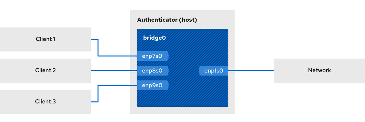
20.1. Install freeradius
# yum install freeradius
If the freeradius package is already installed, delete the /etc/raddb/ directory, uninstall, and then install the package again. Do not use the yum reinstall command to reinstall packages as the permissions and symlinks in the /etc/raddb/ directory will be different.
20.2. Setting up the bridge on the authentication host
A bridge is a link-layer device that forwards traffic between a host and a network based on a table of MAC addresses. If the host is set up as an 802.1X authenticator, add the interface on which to authenticate and the LAN interface to the bridge.
Prerequisites
- The host has multiple NIC interfaces
Procedure
- Create a bridge:
# nmcli connection add type bridge con-name br0 ifname br0 - Assign the Ethernet interface to the bridge:
# nmcli connection add type ethernet slave-type bridge con-name br0-port1 ifname enp1s0 master br0 # nmcli connection add type ethernet slave-type bridge con-name br0-port2 ifname enp7s0 master br0 # nmcli connection add type ethernet slave-type bridge con-name br0-port3 ifname enp8s0 master br0 # nmcli connection add type ethernet slave-type bridge con-name br0-port4 ifname enp9s0 master br0 - Enable the bridge to forward Extensible Authentication Protocol over LAN (EAPOL) packets:
# nmcli connection modify br0 group-forward-mask 8 - Configure the connection to automatically activate the port:
# nmcli connection modify br0 connection.autoconnect-slaves 1 - Activate network card connection:
# nmcli connection up br0
Verification
- Display the status of devices acting as bridge ports:
# ip link show master br0 3: enp1s0: <BROADCAST,MULTICAST,UP,LOWER_UP> mtu 1500 qdisc fq_codel master br0 state UP mode DEFAULT group default qlen 1000 link/ether 52:54:00:62:61:0e brd ff:ff:ff:ff:ff:ff ... - Check to see if forwarding of EAPOL packets is enabled on br0:
# cat /sys/class/net/br0/bridge/group_fwd_mask 0x8
If the return value is 0x8 , forwarding is enabled.
20.3. Certificate Requirements for FreeRADIUS
When using the FreeRADIUS security service, you need different TLS certificates for different purposes:
- A TLS server certificate for encrypted connections to the server. Use a trusted certificate authority (CA) to issue certificates. The server certificate requires the Extended Key Usage (EKU) field to be set to TLS Web Server Authentication.
- A client certificate issued by the same CA for Extensible Authentication Protocol-Transport Layer Security (EAP-TLS). EAP-TLS provides certificate-based authentication and is enabled by default. Client certificates need to have their EKU field set to TLS Web Client Authentication.
If you want to keep your connection private, use your company's CA or create your own to issue certificates for FreeRADIUS. If you use a public CA, you will allow it to authenticate users and issue client certificates for EAP-TLS.
20.4. On the FreeRADIUS server, create a set of test certificates
For testing purposes, the freeradius package installs scripts and configuration files in the /etc/raddb/certs/ directory to create its own Certificate Authority (CA) and issue certificates.
If you use the default configuration, these scripts generate certificates that expire after 60 days and keys that use insecure passwords ("whatever"). You can also customize CA, server, and client configurations.
Follow the process to create the following required files:
- /etc/raddb/certs/ca.pem: CA certificate
- /etc/raddb/certs/server.key: the private key of the server certificate
- /etc/raddb/certs/server.pem: server certificate
- /etc/raddb/certs/client.key: the private key of the client certificate
- /etc/raddb/certs/client.pem: client certificate
Prerequisites
- freeradius is installed.
Procedure
- Enter the /etc/raddb/certs/ directory:
# cd /etc/raddb/certs/ - Optional: Custom CA configuration ca.conf:
... [ req ] default_bits = 2048 input_password = ca_password output_password = ca_password ... [certificate_authority] countryName = US stateOrProvinceName = North Carolina localityName = Raleigh organizationName = Example Inc. emailAddress = admin@example.org commonName = "Example Certificate Authority" ... - Optional: Customize the server configuration server.cnf:
... [ CA_default ] default_days = 730 ... [ req ] distinguished_name = server default_bits = 2048 input_password = key_password output_password = key_password ... [server] countryName = US stateOrProvinceName = North Carolina localityName = Raleigh organizationName = Example Inc. emailAddress = admin@example.org commonName = "Example Server Certificate" ... - Optional: Customize client configuration client.cnf:
... [ CA_default ] default_days = 365 ... [ req ] distinguished_name = client default_bits = 2048 input_password = password_on_private_key output_password = password_on_private_key ... [client] countryName = US stateOrProvinceName = North Carolina localityName = Raleigh organizationName = Example Inc. emailAddress = user@example.org commonName = user@example.org ... - Create a certificate:
# make all - Change the group in the /etc/raddb/certs/server.pem file to radiusd :
# chgrp radiusd /etc/raddb/certs/server.pem*
20.5. Configuring FreeRADIUS to securely authenticate network clients using EAP
FreeRADIUS supports different Extensible Authentication Protocols (EAP). However, for network security purposes, this document describes how to configure FreeRADIUS to support the following secure EAP authentication methods:
- EAP-TLS (Transport Layer Security Protocol) uses a secure TLS connection to authenticate clients using certificates. To use EAP-TLS, you need a TLS client certificate for each network client, and a server certificate for the server. Note that the same Certificate Authority (CA) must have issued the certificate. Always use your own CA to create certificates, as all client certificates issued by the CA you use can authenticate to the FreeRADIUS server.
- EAP-TTLS (Tunneled Transport Layer Security Protocol) uses a secure TLS connection and uses mechanisms such as Password Authentication Protocol (PAP) or Challenge-Handshake Authentication Protocol (CHAP) to authenticate clients. To use EAP-TTLS, you need a TLS server certificate.
- EAP-PEAP (Protected Authentication Protocol) sets up a tunnel using a secure TLS connection as the external authentication protocol. The authenticator verifies the certificate of the RADIUS server. The supplicant then authenticates through a tunnel encrypted using Microsoft Challenge Handshake Authentication Protocol version 2 (MS-CHAPv2) or other methods. The default FreeRADIUS configuration file acts as a document describing all parameters and directives. If you want to disable certain features, please comment them out instead of deleting the corresponding section in the configuration file. This lets you preserve the structure of your configuration files and included documentation.
Prerequisites
- Freeradius is installed.
- The configuration files in the /etc/raddb/ directory remain unchanged, as provided by the freeradius software.
- The following files exist on the server:
- TLS private key of the FreeRADIUS host: /etc/raddb/certs/server.key
- TLS server certificate for FreeRADIUS host: /etc/raddb/certs/server.pem
- TLS CA certificate: /etc/raddb/certs/ca.pem If you store the files in a different location or they have different names, set the private_key_file, certificate_file and ca_file parameters accordingly in the /etc/raddb/mods-available/eap file.
Procedure
- Create /etc/raddb/certs/dh with Diffie-Hellman (DH) parameters if it does not exist. For example, to create a DH file with 2048-bit primes, enter:
#openssl dhparam -out /etc/raddb/certs/dh 2048
To be on the safe side, do not use DH files with primes smaller than 2048 bits. Depending on the number of bits, file creation may take several minutes. 2. Set security permissions on TLS private keys, server certificates, CA certificates, and files using DH parameters:
# chmod 640 /etc/raddb/certs/server.key /etc/raddb/certs/server.pem /etc/raddb/certs/ca.pem /etc/raddb/certs/dh
# chown root:radiusd /etc/raddb/certs/server.key /etc/raddb/certs/server.pem /etc/raddb/certs/ca.pem /etc/raddb/certs/dh
-
Edit the /etc/raddb/mods-available/eap file:
-
Set the password for the private key in the private_key_password parameter:
eap {
...
tls-config tls-common {
...
private_key_password = key_password
...
}
}
- Depending on your environment, set the default_eap_type parameter in the eap directive to the primary EAP type you are using:
eap {
...
default_eap_type = ttls
...
}
For security, use only ttls, tls or peap. 3. Comment out the md5 directive to disable the insecure EAP-MD5 authentication method:
eap {
...
# md5 {
# }
...
}
authenticate {
...
# Auth-Type PAP {
# pap
# }
# Auth-Type CHAP {
# chap
# }
# Auth-Type MS-CHAP {
# mschap
# }
# mschap
# digest
...
}
This only enables EAP and disables the plain text authentication method. 5. Edit the /etc/raddb/clients.conf file: 1. Set secure passwords in localhost and localhost_ipv6 client directives:
client localhost {
ipaddr = 127.0.0.1
...
secret = client_password
...
}
client localhost_ipv6 {
ipv6addr = ::1
secret = client_password
}`` 2. If RADIUS clients on remote hosts (such as network authenticators) should be able to access the FreeRADIUS service, add the corresponding client directives for them: ``
client hostapd.example.org {
ipaddr = 192.0.2.2/32
secret = client_password
}
example_user Cleartext-Password := "user_password"
- Verify configuration file:
# radiusd -XC
...
Configuration appears to be OK
- Enable and start the radiusd service:
# systemctl enable --now radiusd
Troubleshooting
- Stop the radiusd service:
# systemctl stop radiusd
- Start the service in debug mode:
# radiusd -X
...
Ready to process requests
- Perform verification tests on the FreeRADIUS host, as described in sections 20.7, 20.8.
20.6. Configuring hostapd as an authenticator on a wired network
The Host Access Point Daemon (hostapd) service acts as an authenticator on a wired network to provide 802.1X authentication. For this, the hostapd service requires a RADIUS server to authenticate clients.
The hostapd service provides an integrated RADIUS server. However, use the integrated RADIUS server for testing purposes only. For a production environment, use the FreeRADIUS server, which supports additional features such as different authentication methods and access control.
The hostapd service does not interact with the traffic plane. The service only acts as an authenticator. For example, use a script or service that uses the hostapd control interface to allow or deny traffic based on the results of authentication events.
Prerequisites
- The hostapd package is installed
- The FreeRADIUS server is configured to authenticate clients.
Procedure
- Create the /etc/hostapd/hostapd.conf file with the following content:
# General settings of hostapd
# ===========================
# Control interface settings
ctrl_interface=/var/run/hostapd
ctrl_interface_group=wheel
# Enable logging for all modules
logger_syslog=-1
logger_stdout=-1
# Log level
logger_syslog_level=2
logger_stdout_level=2
# Wired 802.1X authentication
# ===========================
# Driver interface type
driver=wired
# Enable IEEE 802.1X authorization
ieee8021x=1
# Use port access entry (PAE) group address
# (01:80:c2:00:00:03) when sending EAPOL frames
use_pae_group_addr=1
# Network interface for authentication requests
interface=br0
# RADIUS client configuration
# ===========================
# Local IP address used as NAS-IP-Address
own_ip_addr=192.0.2.2
# Unique NAS-Identifier within scope of RADIUS server
nas_identifier=hostapd.example.org
# RADIUS authentication server
auth_server_addr=192.0.2.1
auth_server_port=1812
auth_server_shared_secret=client_password
# RADIUS accounting server
acct_server_addr=192.0.2.1
acct_server_port=1813
acct_server_shared_secret=client_password
For details on the parameters used in this configuration, see the description in the /usr/share/doc/hostapd/hostapd/hostapd.conf sample configuration file. 2. Enable the hostapd service:
# systemctl enable --now hostapd
Troubleshooting
- Stop the radiusd service:
# systemctl stop radiusd
- Start the service in debug mode:
# radiusd -X
...
Ready to process requests
- Perform verification tests on the FreeRADIUS host, as described in sections 20.7, 20.8.
20.7. Testing EAP-TTLS Authentication Against a FreeRADIUS Server or Authenticator
To test that authentication using Extensible Authentication Protocol (EAP-TTLS) over Tunneled Transport Layer Security (EAP-TTLS) works as expected, run this flow:
- Set up a FreeRADIUS server.
- Set hostapd service as 802.1X network authentication authenticator.
The output from the testing tools used in this process provides additional information about EAP communication that can help you debug issues.
Prerequisites
- When you want to verify:
- FreeRADIUS server:
- The eapol_test tool provided by the hostapd package is installed.
- The client you are running this process on is already authorized in the FreeRADIUS server's client database.
- The validator wpa_supplicant tool provided by the package of the same name is installed.
- You stored your Certificate Authority (CA) certificate in the /etc/pki/tls/certs/ca.pem file.
Procedure
- Create the /etc/wpa_supplicant/wpa_supplicant-TTLS.conf file with the following content:
ap_scan=0 network={ eap=TTLS eapol_flags=0 key_mgmt=IEEE8021X # Anonymous identity (sent in unencrypted phase 1) # Can be any string anonymous_identity="anonymous" # Inner authentication (sent in TLS-encrypted phase 2) phase2="auth=PAP" identity="example_user" password="user_password" # CA certificate to validate the RADIUS server's identity ca_cert="/etc/pki/tls/certs/ca.pem" } - To authenticate to:
-
FreeRADIUS server, enter:
# eapol_test -c /etc/wpa_supplicant/wpa_supplicant-TTLS.conf -a 192.0.2.1 -s client_password ... EAP: Status notification: remote certificate verification (param=success) ... CTRL-EVENT-EAP-SUCCESS EAP authentication completed successfully ... SUCCESSThe -a option defines the IP address of the FreeRADIUS server, while the -s option specifies the password of the host on which you want to run the commands in the FreeRADIUS server's client configuration. - Authenticator, please enter:
# wpa_supplicant -c /etc/wpa_supplicant/wpa_supplicant-TTLS.conf -D wired -i enp0s31f6 ... enp0s31f6: CTRL-EVENT-EAP-SUCCESS EAP authentication completed successfully ...The -i option specifies the name of the network interface on which wpa_supplicant sends Extensible Authentication Protocol over LAN (EAPOL) packets. For more debugging information, pass the -d option to the command.
20.8. Testing EAP-TLS Authentication Against a FreeRADIUS Server or Authenticator
To test that authentication using Extensible Authentication Protocol (EAP) Transport Layer Security (EAP-TLS) works as expected, follow this process:
- Set up a FreeRADIUS server.
- Set hostapd service as 802.1X network authentication authenticator.
The output from the testing tools used in this process provides additional information about EAP communication that can help you debug issues.
Prerequisites
- When you want to verify:
- FreeRADIUS server:
- The eapol_test tool provided by the hostapd package is installed.
- The client on which you are running this Procedure is authorized in the FreeRADIUS server's client database.
- The validator wpa_supplicant tool provided by the package of the same name is installed.
- You stored the Certificate Authority (CA) certificate in the /etc/pki/tls/certs/ca.pem file.
- The CA that issued the client certificate is the same CA that issued the FreeRADIUS server's server certificate.
- You store client certificates in the /etc/pki/tls/certs/client.pem file.
- Store the client's private key in /etc/pki/tls/private/client.key
Procedure
- Create the /etc/wpa_supplicant/wpa_supplicant-TTLS.conf file with the following content:
ap_scan=0 network={ eap=TLS eapol_flags=0 key_mgmt=IEEE8021X identity="user@example.org" client_cert="/etc/pki/tls/certs/client.pem" private_key="/etc/pki/tls/private/client.key" private_key_passwd="password_on_private_key" # CA certificate to validate the RADIUS server's identity ca_cert="/etc/pki/tls/certs/ca.pem" } - To authenticate to:
-
FreeRADIUS server, enter:
# eapol_test -c /etc/wpa_supplicant/wpa_supplicant-TLS.conf -a 192.0.2.1 -s client_password ... EAP: Status notification: remote certificate verification (param=success) ... CTRL-EVENT-EAP-SUCCESS EAP authentication completed successfully ... SUCCESSThe -a option defines the IP address of the FreeRADIUS server, while the -s option specifies the password of the host on which you want to run the commands in the FreeRADIUS server's client configuration. - Authenticator, please enter:
# wpa_supplicant -c /etc/wpa_supplicant/wpa_supplicant-TLS.conf -D wired -i enp0s31f6 ... enp0s31f6: CTRL-EVENT-EAP-SUCCESS EAP authentication completed successfully ...The -i option specifies the name of the network interface on which wpa_supplicant sends Extensible Authentication Protocol over LAN (EAPOL) packets. For more debugging information, pass the -d option to the command.
20.9. Block and allow traffic based on hostapd authentication events
The hostapd service does not interact with the traffic plane. The service only acts as an authenticator. However, you can write a script to allow or deny traffic based on the outcome of the authentication event.
This Procedure is not supported and there is no enterprise-level solution. It only demonstrates how to block or allow traffic by evaluating the events retrieved by hostapd_cli.
When the 802-1x-tr-mgmt systemd service is started, OpenCloudOS prevents hostapd from listening to all traffic on the port except Extensible Authentication Protocol over LAN (EAPOL) packets, and uses the hostapd_cli tool to connect to the hostapd control interface. The /usr/local/bin/802-1x-tr-mgmt script then evaluates the events. Depending on the different events received by hostapd_cli, the script allows or blocks traffic for a MAC address. Note that when the 802-1x-tr-mgmt service is stopped, all traffic is automatically allowed.
Execute this Procedure on the hostapd server.
Prerequisites
- The hostapd service is configured and the service is ready to authenticate clients.
Procedure
- Create the /usr/local/bin/802-1x-tr-mgmt file with the following content:
#!/bin/sh
if [ "x$1" == "xblock_all" ]
then
nft delete table bridge tr-mgmt-br0 2>/dev/null || true
nft -f - << EOF
table bridge tr-mgmt-br0 {
set allowed_macs {
type ether_addr
}
chain accesscontrol {
ether saddr @allowed_macs accept
ether daddr @allowed_macs accept
drop
}
chain forward {
type filter hook forward priority 0; policy accept;
meta ibrname "br0" jump accesscontrol
}
}
EOF
echo "802-1x-tr-mgmt Blocking all traffic through br0. Traffic for given host will be allowed after 802.1x authentication"
elif [ "x$1" == "xallow_all" ]
then
nft delete table bridge tr-mgmt-br0
echo "802-1x-tr-mgmt Allowed all forwarding again"
fi
case ${2:-NOTANEVENT} in
AP-STA-CONNECTED | CTRL-EVENT-EAP-SUCCESS | CTRL-EVENT-EAP-SUCCESS2)
nft add element bridge tr-mgmt-br0 allowed_macs { $3 }
echo "$1: Allowed traffic from $3"
;;
AP-STA-DISCONNECTED | CTRL-EVENT-EAP-FAILURE)
nft delete element bridge tr-mgmt-br0 allowed_macs { $3 }
echo "802-1x-tr-mgmt $1: Denied traffic from $3"
;;
esac
- Create the /etc/systemd/system/802-1x-tr-mgmt@.service systemd service file with the following content:
[Unit]
Description=Example 802.1x traffic management for hostapd
After=hostapd.service
After=sys-devices-virtual-net-%i.device
[Service]
Type=simple
ExecStartPre=-/bin/sh -c '/usr/sbin/tc qdisc del dev %i ingress > /dev/null 2>&1'
ExecStartPre=-/bin/sh -c '/usr/sbin/tc qdisc del dev %i clsact > /dev/null 2>&1'
ExecStartPre=/usr/sbin/tc qdisc add dev %i clsact
ExecStartPre=/usr/sbin/tc filter add dev %i ingress pref 10000 protocol 0x888e matchall action ok index 100
ExecStartPre=/usr/sbin/tc filter add dev %i ingress pref 10001 protocol all matchall action drop index 101
ExecStart=/usr/sbin/hostapd_cli -i %i -a /usr/local/bin/802-1x-tr-mgmt
ExecStopPost=-/usr/sbin/tc qdisc del dev %i clsact
[Install]
WantedBy=multi-user.target
- Reload systemd:
# systemctl daemon-reload
- Start the 802-1x-tr-mgmt service that the interface hostapd is listening on:
# systemctl enable --now 802-1x-tr-mgmt@br0.service
Chapter 21 Authenticating clients to the network using the 802.1X standard with certificates stored on the file system
Administrators typically use port-based Network Access Control (NAC) based on the IEEE 802.1X standard to protect the network from unauthorized LAN and Wi-Fi clients. The steps in this chapter describe the different options for configuring network authentication.
21.1. Configuring 802.1X Network Authentication on an Existing Ethernet Connection Using nmcli
Using the nmcli tool, you can configure clients to authenticate to the network. This section describes how to configure TLS authentication in an existing Ethernet connection profile named enp1s0 to authenticate to the network.
Prerequisites
- The network supports 802.1X network authentication.
- The Ethernet connection profile exists in NetworkManager and has a valid IP configuration.
-
The following files required for TLS authentication are present on the client:
-
The client key is stored in the /etc/pki/tls/private/client.key file, which is owned by and readable only by root.
- Client certificates are stored in the /etc/pki/tls/certs/client.crt file.
- Certificate Authority (CA) certificates are stored in the /etc/pki/tls/certs/ca.crt file.
- The wpa_supplicant package is installed.
Procedure
- Set Extensible Authentication Protocol (EAP) to tls and path to client certificate and key files:
# nmcli connection modify enp1s0 802-1x.eap tls 802-1x.client-cert /etc/pki/tls/certs/client.crt 802-1x.private-key /etc/pki/tls/certs/certs/client.key
Note that you must set the 802-1x.eap, 802-1x.client-cert, and 802-1x.private-key parameters in the same command. 2. Set the path to the CA certificate:
# nmcli connection modify enp1s0 802-1x.ca-cert /etc/pki/tls/certs/ca.crt
# nmcli connection modify enp1s0 802-1x.identity user@example.com
# nmcli connection modify enp1s0 802-1x.private-key-password password
By default, NetworkManager saves passwords in clear text in the /etc/sysconfig/network-scripts/keys-connection_name file, which is only readable by the root user. However, clearing text passwords in configuration files has security implications.
For increased security, set the 802-1x.password-flags parameter to 0x1. With this setup, on servers with the GNOME desktop environment or running nm-applet, NetworkManager can retrieve passwords from these services. In other cases, NetworkManager will prompt for a password. 5. Activate the connection profile:
# nmcli connection up enp1s0
21.2. Configuring Static Ethernet Connections with 802.1X Network Authentication Using nmstatectl
Prerequisites
- The network supports 802.1X network authentication.
- The Ethernet connection profile exists in NetworkManager and has a valid IP configuration.
- The following files required for TLS authentication are present on the client:
- The client key is stored in the /etc/pki/tls/private/client.key file, which is owned by and readable only by root.
- Client certificates are stored in the /etc/pki/tls/certs/client.crt file.
- Certificate Authority (CA) certificates are stored in the /etc/pki/tls/certs/ca.crt file.
Procedure
- Create the YAML file ~/create-ethernet-profile.yml :
--- interfaces: - name: enp1s0 type: ethernet state: up ipv4: enabled: true address: - ip: 192.0.2.1 prefix-length: 24 dhcp: false ipv6: enabled: true address: - ip: 2001:db8:1::1 prefix-length: 64 autoconf: false dhcp: false 802.1x: ca-cert: /etc/pki/tls/certs/ca.crt client-cert: /etc/pki/tls/certs/client.crt eap-methods: - tls identity: client.example.org private-key: /etc/pki/tls/private/client.key private-key-password: password routes: config: - destination: 0.0.0.0/0 next-hop-address: 192.0.2.254 next-hop-interface: enp1s0 - destination: ::/0 next-hop-address: 2001:db8:1::fffe next-hop-interface: enp1s0 dns-resolver: config: search: - example.com server: - 192.0.2.200 - 2001:db8:1::ffbb - Application configuration:
# nmstatectl apply ~/create-ethernet-profile.yml
Configuring Static Ethernet Connections with 802.1X Network Authentication Using rhel-system-roles
Run this step on the Ansible control node.
Prerequisites
- Ansible and rhel-system-roles packages are installed on the control node.
- If you are running the playbook with a non-root user, make sure that user has appropriate sudo privileges on the managed nodes.
- The network supports 802.1X network authentication.
- The Ethernet connection profile exists in NetworkManager and has a valid IP configuration.
- The following files required for TLS authentication are present on the client:
- The client key is stored in the /etc/pki/tls/private/client.key file, which is owned by and readable only by root.
- Client certificates are stored in the /etc/pki/tls/certs/client.crt file.
- Certificate Authority (CA) certificates are stored in the /etc/pki/tls/certs/ca.crt file.
Procedure
- Add the IP of the host executing the playbook to the /etc/ansible/hosts Ansible inventory:
node.example.com
---
- name: Configure an Ethernet connection with 802.1X authentication
hosts: node.example.com
become: true
tasks:
- name: Copy client key for 802.1X authentication
copy:
src: "/srv/data/client.key"
dest: "/etc/pki/tls/private/client.key"
mode: 0600
- name: Copy client certificate for 802.1X authentication
copy:
src: "/srv/data/client.crt"
dest: "/etc/pki/tls/certs/client.crt"
- name: Copy CA certificate for 802.1X authentication
copy:
src: "/srv/data/ca.crt"
dest: "/etc/pki/ca-trust/source/anchors/ca.crt"
- include_role:
name: rhel-system-roles.network
vars:
network_connections:
- name: enp1s0
type: ethernet
autoconnect: yes
ip:
address:
- 192.0.2.1/24
- 2001:db8:1::1/64
gateway4: 192.0.2.254
gateway6: 2001:db8:1::fffe
dns:
- 192.0.2.200
- 2001:db8:1::ffbb
dns_search:
- example.com
ieee802_1x:
identity: user_name
eap: tls
private_key: "/etc/pki/tls/private/client.key"
private_key_password: "password"
client_cert: "/etc/pki/tls/certs/client.crt"
ca_cert: "/etc/pki/ca-trust/source/anchors/ca.crt"
domain_suffix_match: example.com
state: up
- To connect to a managed host as root, enter:
# ansible-playbook -u root ~/enable-802.1x.yml -
To connect to a managed host as a user, enter:
# ansible-playbook -u user_name --ask-become-pass ~/ethernet-static-IP.ymlThe --ask-become-pass option ensures that the ansible-playbook command prompts for the sudo password for the user defined in the -u user_name option.
If the -u user_name option is not specified, ansible-playbook connects to the managed host as the user currently logged into the control node.
Chapter 22 Managing Default Gateway Settings
A default gateway is a router that forwards network packets when no other route matches the packet's destination. On a local network, the default gateway is usually a host one hop away from the Internet.
22.1. Setting a Default Gateway on an Existing Network Connection Using nmcli
In most cases, administrators will set the default gateway when creating a connection, this section describes how to use the nmcli tool to set or update the default gateway on a previously created connection.
Prerequisites
- At least one static IP address needs to be configured on the connection where the default gateway is set.
- If the user is able to log in at the physical console, the user rights are sufficient. Otherwise, the user must have root privileges.
Procedure
- Set the default gateway IP address. For example, to set the IPv4 address of example's default gateway to 192.0.2.1 :
# nmcli connection modify example ipv4.gateway "192.0.2.1"
Set the IPv6 address of the example's default gateway to 2001:db8:1::1 :
# nmcli connection modify example ipv6.gateway "2001:db8:1::1"
# nmcli connection up example
# ip -4 route
default via 192.0.2.1 dev example proto static metric 100
IPv6:
# ip -6 route
default via 2001:db8:1::1 dev example proto static metric 100 pref medium
22.2. Setting a Default Gateway on an Existing Network Connection Using nmcli Interactive Mode
In most cases, administrators set the default gateway when creating a connection, as described in Configuring Dynamic Ethernet Connections Using the nmcli Interactive Editor .
This section describes how to set or update the default gateway on a previously created connection using the interactive mode of the nmcli tool.
Prerequisites
- Network connections that require a default gateway to have at least one static IP address
- The working user needs to be able to log in at the physical console, otherwise the user must have root privileges
Procedure
- Turn on nmcli interactive mode to configure network connections, for example to connect nmcli interactive mode:
# sudo nmcli connection edit example
nmcli> set ipv4.gateway 192.0.2.1
For example, to set the IPv6 address of the default gateway on the example connection to 2001:db8:1::1 :
nmcli> set ipv6.gateway 2001:db8:1::1
nmcli> print
...
ipv4.gateway: 192.0.2.1
...
ipv6.gateway: 2001:db8:1::1
...
nmcli> save persistent
nmcli> activate example
The network connection is temporarily lost during the reboot. 6. Exit nmcli interactive mode:
nmcli> quit
# ip -4 route
default via 192.0.2.1 dev example proto static metric 100
IPv6:
# ip -6 route
default via 2001:db8:1::1 dev example proto static metric 100 pref medium
22.3. Use nm-connection-editor to set the default gateway for existing network connections
In most cases, administrators set the default gateway when creating a connection. This section describes how to use the nm-connection-editor application to set or update the default gateway on a previously created connection.
Prerequisites
- Network connections that require a default gateway to have at least one static IP address
Procedure
- Enter nm-connection-editor in the terminal:
- Select the connection to modify and click the gear icon to edit an existing connection.
- Set the IPv4 default gateway.
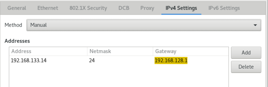
- Set the IPv6 default gateway.
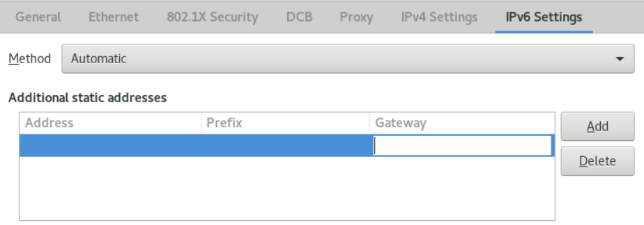
- Click Save.
- Restart the network connection for the changes to take effect. For example, to restart the example connection using the command line:
$ sudo nmcli connection up example
# ip -4 route
default via 192.168.138.1 dev example proto static metric 100
IPv6:
# ip -6 route
default via 2001:db8:1::1 dev example proto static metric 100 pref medium
22.4. Using control-center to set a default gateway for an existing network connection
In most cases, administrators set the default gateway when creating a connection. This section describes how to set or update the default gateway on a previously created connection using the control-center application.
Prerequisites
- Network connections that require a default gateway to have at least one static IP address
- The network connection configuration can be opened in the control-center application.
Procedure
- Enter Settings, select Network, and click the gear on the right side of the network connection to be configured to edit.
- Set the IPv4 default gateway.
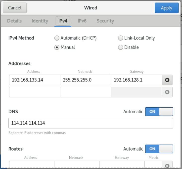
- Set the IPv6 default gateway.
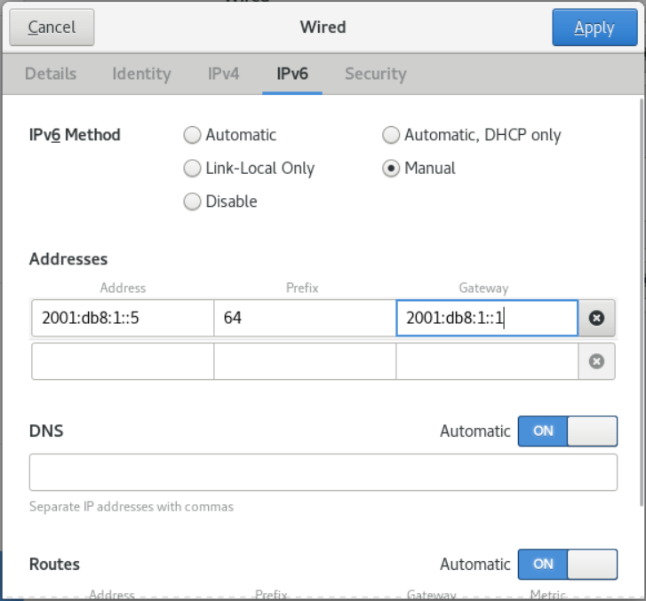
- Click Apply.
- Toggle the configured network connection state to Off and then to On to restart the network connection to apply the changes.
- (Optional) Verify that the route is active. IPv4:
# ip -4 route
default via 192.168.138.1 dev example proto static metric 100
IPv6:
# ip -6 route
default via 2001:db8:1::1 dev example proto static metric 100 pref medium
22.5. Using nmstatectl to Set the Default Gateway for Existing Network Connections
Prerequisites
- Network connections that require a default gateway to have at least one static IP address
- nmstate installed.
Procedure
- Create the ~/set-default-gateway.yml YAML file:
--- routes: config: - destination: 0.0.0.0/0 next-hop-address: 192.0.2.1 next-hop-interface: enp1s0 - App settings:
# nmstatectl apply ~/set-default-gateway.yml
22.6. Using rhel-system-roles to set a default gateway for an existing network connection
When you run a script that uses Networking RHEL system roles, if the value set does not match the name specified in the script, the system role overwrites an existing connection profile with the same name. Therefore, always specify the entire configuration of the network connection profile in the script, even if the IP configuration already exists. Otherwise, role will reset these values to default.
Prerequisites
- The ansible and rhel-system-roles packages are installed on the control node.
- If you are running the playbook as a non-root user, make sure the user you are using has sudo privileges.
Procedure
- Add the host IP or name to the /etc/ansible/hosts Ansible inventory file if the host you are using to execute the instructions in the playbook is not already listed:
node.example.com
---
- name: Configure an Ethernet connection with static IP and default gateway
hosts: node.example.com
become: true
tasks:
- include_role:
name: rhel-system-roles.network
vars:
network_connections:
- name: enp1s0
type: ethernet
autoconnect: yes
ip:
address:
- 198.51.100.20/24
- 2001:db8:1::1/64
gateway4: 198.51.100.254
gateway6: 2001:db8:1::fffe
dns:
- 198.51.100.200
- 2001:db8:1::ffbb
dns_search:
- example.com
state: up
- To connect to a managed host as root, enter:
# ansible-playbook -u root ~/ethernet-connection.yml -
To connect to a managed host as a user, enter:
# ansible-playbook -u user_name --ask-become-pass ~/ethernet-connection.ymlThe --ask-become-pass option ensures that the ansible-playbook command prompts for the sudo password for the user defined in the -u user_name option.
If the -u user_name option is not specified, ansible-playbook connects to the managed host as the user currently logged into the control node.
22.7. Using network scripts to set a default gateway for an existing network connection
Prerequisites
- The NetworkManager package is not installed, or the NetworkManager service is disabled.
- The network-scripts package is installed.
Procedure
- Set the GATEWAY parameter in the /etc/sysconfig/network-scripts/ifcfg-enp1s0 file to 192.0.2.1 :
GATEWAY=192.0.2.1 - Add a default entry to the /etc/sysconfig/network-scripts/route-enp0s1 file:
default via 192.0.2.1 - Restart the network:
# systemctl restart network
22.8. Using NetworkManager to manage multiple default gateways
In some cases, you may need to set more than one default gateway on the host. However, to avoid asynchronous routing issues, each default gateway for the same protocol requires a separate metric value. Note that OpenCloudOS only uses connections to the default gateway set to the lowest routing authority.
You can set metrics for connected IPv4 and IPv6 gateways with the following commands:
# nmcli connection modify connection-name ipv4.route-metric value ipv6.route-metric value
Do not set the same routing metric for the same protocol in multiple connection configuration sets to avoid routing problems.
If you set a default gateway with no routing authority, NetworkManager automatically sets the routing authority based on the interface type. NetworkManager will assign a default value for this network type to the first connection activated, and set an incremental value for each other connection of the same type in the order of activation. For example, if two Ethernet connections with default gateways exist, NetworkManager will set the routing weight to 100 on the default gateway route of the connection you activate first. For the second connection, NetworkManager will be set to 101.
The following is the correspondence between frequently used network types and their default routing rights:
| Connection Type | Default Routing Right |
|---|---|
| VPN | 50 |
| Ethernet | 100 |
| MACsec | 125 |
| InfiniBand | 150 |
| Bond | 300 |
| Team | 350 |
| VLAN | 400 |
| Bridge | 425 |
| TUN | 450 |
| Wi-Fi | 600 |
| IP tunnel | 675 |
22.9. Configuring NetworkManager to prevent specific configuration files from providing a default gateway
You can configure NetworkManager to provide a default gateway without using a specific configuration file. For connection profiles that are not connected to a default gateway, follow the steps below.
Prerequisites
- A NetworkManager connection profile exists for network connections that do not have a default gateway configured.
Procedure
- If the network connection uses a dynamic IP configuration, configure NetworkManager not to use IPv4 and IPv6 default routes:
# nmcli connection modify connection_name ipv4.never-default yes ipv6.never-default yes
Note that setting ipv4.never-default and ipv6.never-default to yes automatically removes the IP address of the default gateway for the corresponding protocol from the connection profile. 2. Activation link:
# nmcli connection up connection_name
Verification
- Use ip -4 route or ip -6 route to verify that the default gateway is enabled.
22.10. Fix unexpected routing behavior due to multiple default gateways
Only in rare cases (such as when using multipath TCP) are multiple default gateways required on a host. In most cases, you only configure a default gateway to avoid unexpected routing behavior or asynchronous routing problems.
Prerequisites
- The host uses NetworkManager to manage network connections.
- The host has multiple network interfaces.
- The host has multiple default gateways configured.
Procedure
- Show routing table:
- IPv4:
# ip -4 route default via 192.0.2.1 dev enp1s0 proto static metric 101 default via 198.51.100.1 dev enp7s0 proto static metric 102 ... -
IPv6:
# ip -6 route default via 2001:db8:1::1 dev enp1s0 proto static metric 101 pref medium default via 2001:db8:2::1 dev enp7s0 proto static metric 102 pref medium ...Entries starting with default indicate the default route. Note the interface names for these entries displayed next to dev. 2. Use the following command to display the NetworkManager connections you identified in the previous step:
# nmcli -f GENERAL.CONNECTION,IP4.GATEWAY,IP6.GATEWAY device show enp1s0 GENERAL.CONNECTION: Corporate-LAN IP4.GATEWAY: 192.168.122.1 IP6.GATEWAY: 2001:db8:1::1 # nmcli -f GENERAL.CONNECTION,IP4.GATEWAY,IP6.GATEWAY device show enp7s0 GENERAL.CONNECTION: Internet-Provider IP4.GATEWAY: 198.51.100.1 IP6.GATEWAY: 2001:db8:2::1
In these examples, profiles named Corporate-LAN and Internet-Provider set default gateways. Because on a local network, the default gateway is usually a host one hop from the Internet, it is incorrect for the remainder of this procedure to assume a default gateway on the Corporate-LAN. 3. To configure NetworkManager not to use the Corporate-LAN connection as the default route for IPv4 and IPv6 connections:
# nmcli connection modify Corporate-LAN ipv4.never-default yes ipv6.never-default yes
# nmcli connection up Corporate-LAN
Verification
- Use ip -4 route or ip -6 route to verify that there is only one gateway.
Chapter 23 Configuring Static Routing
Routing ensures that you can send and receive traffic between interconnected networks. In larger environments, administrators typically configure services so that routers can dynamically learn about other routers. In smaller environments, administrators often configure static routes to ensure that traffic is accessible from one network to the next.
You may need static routing for functional communication between multiple networks if these conditions apply:
- Traffic must pass through multiple networks.
- Insufficient exclusive traffic flow through the default gateway.
23.1. Example of a network that requires static routing
Because not all IP networks are directly connected through a router, some networks will not be able to communicate with each other without static routing. Static routes can also be configured for certain network flows with only one direction.
You can configure static routes as follows:
- Simple Configuration: Set this static route only on Router 1. However, this increases traffic on Router 1, because traffic sent from the data center (host on 203.0.113.0/24) to Network B (198.51.100.0/24) always goes through Router 1 to Router 2.
- Complex configuration: Please configure this static route (203.0.113.0/24) on all hosts in the data center. All hosts on this subnet then send hosts closer to Network B (198.51.100.0/24) directly to Router 2 (203.0.113.10).
For more details, see the description in the diagram below.
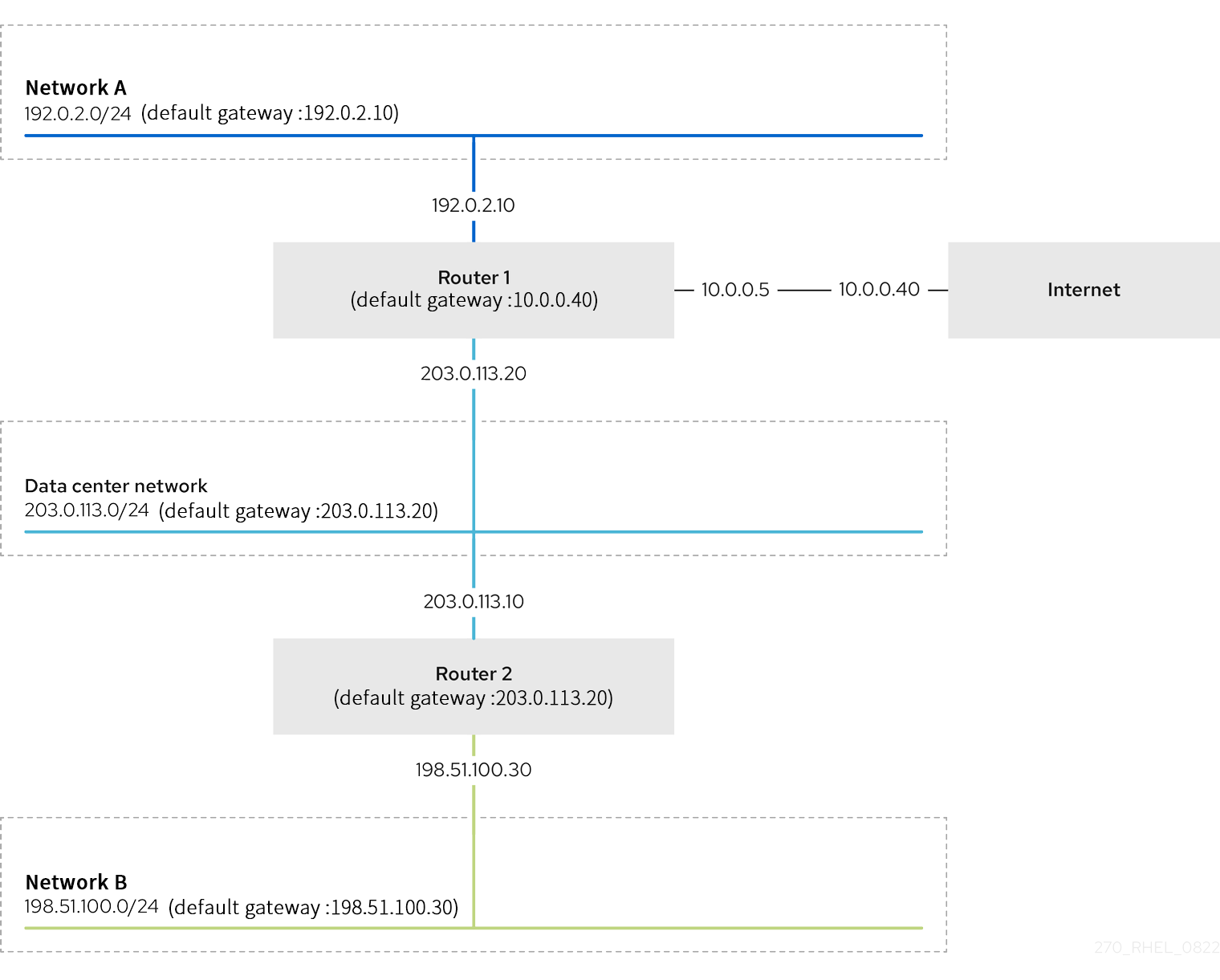
If the required static routes are not configured, the following describes how each network communication works:
-
Hosts in Network A (192.0.2.0/24):
-
Can communicate with other hosts on the same subnet because they are directly connected.
- Can communicate with the Internet because Router 1 is in the Network A network (192.0.2.0/24) and has a default gateway to the Internet.
- Can communicate with Data Center network (203.0.113.0/24) because Router 1 has interfaces in Network A (192.0.2.0/24) and Data Center (203.0.113.0/24) network.
- Unable to communicate with Network B (198.51.100.0/24) because Router 1 has no interface in this network. Therefore, Router 1 sends traffic to its own default gateway (Internet).
-
Hosts in the data center network (203.0.113.0/24):
-
Can communicate with other hosts on the same subnet because they are directly connected.
- Can communicate with the Internet because their default gateway is set to Router 1, which has interfaces on the network, data center (203.0.113.0/24) and the Internet.
- Can communicate with Network A (192.0.2.0/24) because their default gateway is set to Router 1, and Router 1 is in both Data Center (203.0.113.0/24) and Network A (192.0.2.0/24) networks Interface exists.
- Unable to communicate with the Network B network (198.51.100.0/24) because there are no interfaces in this network. So, a host in the datacenter (203.0.113.0/24) sends traffic to its default gateway (Router 1). Router 1 has no interface on Network B (in 198.51.100.0/24), so Router 1 will send this traffic to its own default gateway (Internet).
-
Hosts in the Network B network (198.51.100.0/24):
-
Can communicate with other hosts on the same subnet because they are directly connected.
- Unable to communicate with hosts on the Internet. Router 2 sends traffic to Router 1 because of the default gateway setting. The actual behavior of Router 1 depends on the reverse path filter (rp_filter) system control (sysctl) setting. By default, in OpenCloudOS, Router 1 drops outgoing traffic instead of routing it to the internet. However, regardless of the configured behavior, it is not possible to communicate without a static route.
- Unable to communicate with datacenter network (203.0.113.0/24). Outgoing traffic goes through Router 2 to its destination due to the default gateway setting. However, the reply to the packet does not reach the sender, because the host (203.0.113.0/24) in the data center network sends the reply to its default gateway (Router 1). Router 1 then sends the traffic to the Internet.
- Unable to communicate with Network A (192.0.2.0/24). Router 2 sends traffic to Router 1 because of the default gateway setting. The actual behavior of Router 1 depends on the rp_filter sysctl setting. By default, in OpenCloudOS, Router 1 drops outgoing traffic instead of sending it to Network A (192.0.2.0/24). However, regardless of the configured behavior, it is not possible to communicate without a static route.
Note that in addition to configuring static routing, IP forwarding must be enabled on both routers.
23.2. Introduction to configure static routing with nmcli command
Static routing can be configured with the following command:
$ nmcli connection modify connection_name ipv4.routes "ip[/prefix] [next_hop] [metric] [attribute=value] [attribute=value] ..."
This command supports configuration of the following properties:
- cwnd=n : Set the congestion window (CWND) size, defined by the number of packets.
- lock-cwnd=true|false : Defines whether the kernel can update the CWND value.
- lock-mtu=true|false : Defines whether the kernel can update the MTU to the path MTU (PMTU).
- lock-window=true|false : Defines whether the kernel can update the maximum window size of TCP packets.
- mtu=n : Set the maximum transmission unit (MTU) of the path to the destination address.
- onlink=true|false : Defines whether the next hop is directly attached to this link, even if it does not match any interface prefix.
- scope=n: For IPv4 routing, this property sets the scope of destinations covered by the routing prefix. Set the value to an integer (0-255).
- src=address : Make the source address preferred when sending traffic to destinations covered by the route prefix.
- table=table_id : Set the ID of the table the route should be added to. If this parameter is omitted, NetworkManager will use the main table.
- tos=n : Set the Type of Service (TOS) key. Set the value to an integer (0-255).
- type=value : Set the route type. NetworkManager supports unicast, local, blackhole, unreachable, prohibit, and throw route types. The default is unicast.
- window=n : Set the maximum window size in bytes for TCP advertisements to these destinations.
If the ipv4.routes subcommand is used, nmcli will override any current settings for this parameter.
Add a route:
$ nmcli connection modify connection_name +ipv4.routes "..."
Delete a route:
$ nmcli connection modify connection_name -ipv4.routes "..."
23.3. Configuring Static Routing Using the nmcli Command
You can add a static route to the network connection configuration using the nmcli connection modify command.
The Procedure in this section describes how to add a route to the 192.0.2.0/24 network using a gateway running on 198.51.100.1 that is reachable via the example connection.
Prerequisites
- network configured
- The gateway of the static route must be directly reachable on the interface.
- The user needs to be able to log in at the physical console. Otherwise, the command requires root privileges.
Procedure
- Add a static route to the example connection:
$ sudo nmcli connection modify example +ipv4.routes "192.0.2.0/24 198.51.100.1"
To set multiple routes in one step, separate each static route passed to the command with a comma. For example, to add routes to the 192.0.2.0/24 and 203.0.113.0/24 networks, both routed through the 198.51.100.1 gateway, enter:
$ sudo nmcli connection modify example +ipv4.routes "192.0.2.0/24 198.51.100.1, 203.0.113.0/24 198.51.100.1"
$ nmcli connection show example
...
ipv4.routes: { ip = 192.0.2.1/24, nh = 198.51.100.1 }
...
$ sudo nmcli connection up example
$ ip route
...
192.0.2.0/24 via 198.51.100.1 dev example proto static metric 100
23.4. Using control-center to configure static routing
You can use control-center in GNOME to add static routes to your networking configuration.
The Procedure in this section describes how to add a route to the 192.0.2.0/24 network, which uses a gateway running on 198.51.100.1.
Prerequisites
- The network is configured.
- The gateway of the static route must be directly reachable on the interface.
- The connected network configuration can be opened in the control-center application.
Procedure
- Enter the settings, select Network, and click the gear in the network entry that needs to add a static route to edit.
- (Optional) Disable automatic routing so that only static routes are used by clicking the On button in the Routes section of the IPv4 tab. If autorouting is enabled, OpenCloudOS will use static routes and routes received from a DHCP server.
- Enter the address, subnet mask, gateway and routing rights (optional):
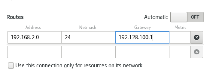
- Click Apply.
- Back in the Network window, re-enable the connection to apply the changes by toggling the connection's button to Off and then back to On.
- (Optional) Verify that the route is active:
$ ip route
...
192.0.2.0/24 via 198.51.100.1 dev example proto static metric 100
23.5. Configuring Static Routing Using nm-connection-editor
You can add static routes to your network connection configuration using the nm-connection-editor application.
The Procedure in this section describes how to add a route to the 192.0.2.0/24 network using a gateway running on 198.51.100.1 which is reachable via the example connection.
Prerequisites
- The network is configured.
- The gateway of the static route must be directly reachable on the interface.
Procedure
- Enter in the terminal:
- Select the example connection and click the gear icon to edit the connection.
- Open the IPv4 tab.
- Click the Route button.
- Click the Add button and enter the address, subnet mask, gateway, and routing rights (optional).
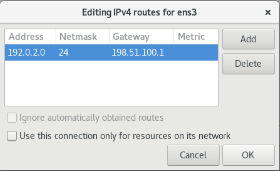
- Click OK.
- Click Save.
- Restart the network to apply the changes.
$ sudo nmcli connection up example
$ ip route
...
192.0.2.0/24 via 198.51.100.1 dev example proto static metric 100
23.6. Configuring Static Routing Using nmcli Interactive Mode
You can add static routes to your networking configuration using the interactive mode of the nmcli tool.
The Procedure in this section describes how to add a route to the 192.0.2.0/24 network using a gateway running on 198.51.100.1 which is reachable via the example connection.
Prerequisites
- network configured
- Gateways for static routes must be directly accessible on the interface.
- The user needs to be able to log in at the physical console. Otherwise, the command requires root privileges.
Procedure
- Edit example using nmcli interactive mode:
$ sudo nmcli connection edit example - Add a static route:
nmcli> set ipv4.routes 192.0.2.0/24 198.51.100.1 - (Optional) Verify that the route was correctly added to the configuration:
nmcli> print ... ipv4.routes: { ip = 192.0.2.1/24, nh = 198.51.100.1 } ...
The ip attribute corresponds to the network to be routed, and the nh attribute corresponds to the gateway (next hop). 4. Save configuration:
nmcli> save persistent
nmcli> activate example
nmcli> quit
$ ip route
...
192.0.2.0/24 via 198.51.100.1 dev example proto static metric 100
23.7. Configuring Static Routing Using nmstatectl
You can add static routes to your networking configuration using the nmstatectl tool.
The Procedure in this section describes how to add a route to the 192.0.2.0/24 network, which uses a gateway running on 198.51.100.1, which is reachable through the example network interface.
Prerequisites
- The example network interface is configured.
- Gateways for static routes must be directly reachable on the network interface.
- The nmstate package is installed.
Procedure
- Create a YAML file ~/add-static-route-to-enp1s0.yml with the following content:
--- routes: config: - destination: 192.0.2.0/24 next-hop-address: 198.51.100.1 next-hop-interface: enp1s0 - App settings:
# nmstatectl apply ~/add-static-route-to-enp1s0.yml
23.8. Configuring Static Routing Using rhel-system-roles
When you run a script that uses Networking RHEL system roles, if the value set does not match the name specified in the script, the system role overwrites an existing connection profile with the same name. Therefore, always specify the entire configuration of the network connection profile in the script, even if the IP configuration already exists. Otherwise, role will reset these values to default.
Prerequisites
- The ansible and rhel-system-roles packages are installed on the control node.
- If you are running the playbook as a non-root user, make sure the user you are using has sudo privileges.
Procedure
- Add the host IP or name to the /etc/ansible/hosts Ansible inventory file if the host you are using to execute the instructions in the playbook is not already listed:
node.example.com
---
- name: Configure an Ethernet connection with static IP and additional routes
hosts: node.example.com
become: true
tasks:
- include_role:
name: rhel-system-roles.network
vars:
network_connections:
- name: enp7s0
type: ethernet
autoconnect: yes
ip:
address:
- 198.51.100.20/24
- 2001:db8:1::1/64
gateway4: 198.51.100.254
gateway6: 2001:db8:1::fffe
dns:
- 198.51.100.200
- 2001:db8:1::ffbb
dns_search:
- example.com
route:
- network: 192.0.2.0
prefix: 24
gateway: 198.51.100.1
- network: 203.0.113.0
prefix: 24
gateway: 198.51.100.2
state: up
- To connect to a managed host as root, enter:
# ansible-playbook -u root ~/add-static-routes.yml -
To connect to a managed host as a user, enter:
# ansible-playbook -u user_name --ask-become-pass ~/add-static-routes.ymlThe --ask-become-pass option ensures that the ansible-playbook command prompts for the sudo password for the user defined in the -u user_name option.
If the -u user_name option is not specified, ansible-playbook connects to the managed host as the user currently logged into the control node.
Verification
- Show routing table:
# ip -4 route default via 198.51.100.254 dev enp7s0 proto static metric 100 192.0.2.0/24 via 198.51.100.1 dev enp7s0 proto static metric 100 203.0.113.0/24 via 198.51.100.2 dev enp7s0 proto static metric 100 ...
23.9. Use network scripts to create static routing configuration files in key-value pair format
This section Procedure describes how to manually create a routing configuration file for IPv4 routing to the 192.0.2.0/24 network when using network scripts instead of NetworkManager. In this example, the corresponding gateway with IP address 198.51.100.1 is reachable through the enp1s0 interface.
The examples in this Procedure use configuration entries in key-value-format.
Note that network scripts only support the key-value format for static IPv4 routes. For IPv6 routing, use ip-command-format.
Prerequisites
- The gateway of the static route must be directly reachable on the interface.
- The NetworkManager package is not installed, or the NetworkManager service is disabled.
- The network-scripts package is installed.
Procedure
- Add a static IPv4 route to the /etc/sysconfig/network-scripts/route-enp0s1 file:
ADDRESS0=192.0.2.0
NETMASK0=255.255.255.0
GATEWAY0=198.51.100.1
- The ADDRESS0 variable defines the network of the first routing entry.
- The NETMASK0 variable defines the subnet mask of the first route entry.
- The GATEWAY0 variable defines the IP address of the gateway to the remote network or the host of the first routing entry.
If you add multiple static routes, increase the number of variable names. Note that variables for each route must be numbered sequentially. For example, ADDRESS0, ADDRESS1, ADDRESS3, and so on. 2. Restart the network:
# systemctl restart network
23.10. Use network scripts to create static routing configuration files in ip-command-format format
This section Procedure describes how to use network scripts to manually create routing configuration files for the following static routes:
- IPv4 routing to the 192.0.2.0/24 network. The corresponding gateway with IP address 198.51.100.1 can be accessed through the enp1s0 interface.
- IPv6 routing to the 2001:db8:1::/64 network. The corresponding gateway with IP address 2001:db8:2::1 can be accessed through the enp1s0 interface.
The examples in this Procedure use configuration entries in ip-command-format.
Prerequisites
- Gateways for static routes must be directly reachable on the network interface.
- The NetworkManager package is not installed, or the NetworkManager service is disabled.
- The network-scripts package is installed.
Procedure
- Add a static IPv4 route to the /etc/sysconfig/network-scripts/route-enp0s1 file:
192.0.2.0/24 via 198.51.100.1 dev enp0s1 - Add a static IPv6 route to the /etc/sysconfig/network-scripts/route6-enp0s1 file:
2001:db8:1::/64 via 2001:db8:2::1 dev enp0s1 - Restart the network:
# systemctl restart network
Chapter 24 Configuring Policy Routing to Define Additional Routes
By default, the kernel in OpenCloudOS decides to use routing tables to forward network packets based on their destination addresses. Policy routing allows you to configure complex routing scenarios. For example, you can route packets based on various criteria, such as source address, packet metadata, or protocol.
This section discusses how to configure policy routing with NetworkManager.
Note that on systems using NetworkManager, only the nmcli tool supports setting routing rules and assigning routes to specific tables.
24.1. Using NetworkManager to route traffic for a specific subnet to a different default gateway
This section describes how to configure OpenCloudOS with a default route to route all traffic to Internet Provider A's router. Using policy routing, OpenCloudOS will route traffic received from the internal workstation subnet to provider B.
The Procedure network topology is as follows:
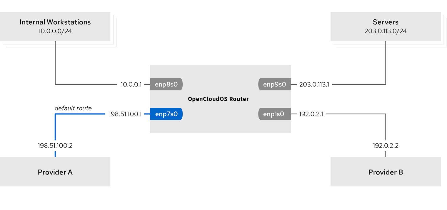
Prerequisites
- The system uses NetworkManager to configure the network.
- The router to be configured in Procedure has four network interfaces:
- The enp7s0 interface is connected to Provider A's network. The gateway IP in the provider network is 198.51.100.2 and the network uses a /30 netmask.
- The enp1s0 interface is connected to Provider B's network. The gateway IP in the provider network is 192.0.2.2 and the network uses a /30 netmask.
- The enp8s0 interface is connected to the 10.0.0.0/24 subnet with internal workstations attached.
- The enp9s0 interface is connected to the 203.0.113.0/24 subnet to which the company server is attached.
- Hosts in the internal workstation subnet use 10.0.0.1 as the default gateway. In this Procedure, you assign this IP address to the router's enp8s0 network interface.
- Hosts in the server subnet use 203.0.113.1 as the default gateway. In this Procedure, you assign this IP address to the router's enp9s0 network interface.
- The firewalld service is enabled and active.
Procedure
- Configure the network interface as Provider A:
# nmcli connection add type ethernet con-name Provider-A ifname enp7s0 ipv4.method manual ipv4.addresses 198.51.100.1/30 ipv4.gateway 198.51.100.2 ipv4.dns 198.51.100.200 connection.zone external
The nmcli connection add command creates a NetworkManager connection profile. The option parameters for this command are described below:
- type ethernet : Define the connection type as Ethernet.
- con-name connection_name : Set the name of the configuration file. Use meaningful names to avoid confusion.
- ifname network_device : The configured network interface.
- ipv4.method manual: Allows configuration of static IP addresses.
- ipv4.addresses IP_address/subnet_mask : Set IPv4 address and subnet mask.
- ipv4.gateway IP_address : Set the default gateway address.
- ipv4.dns IP_of_DNS_server : Set the IPv4 address of the DNS server.
- connection.zone firewalld_zone : Assign a network interface to the defined firewalld zone. Note that firewalld automatically enables masquerading for interfaces assigned to the external zone.
- Configure the network interface as Provider B:
# nmcli connection add type ethernet con-name Internal-Workstations ifname enp8s0 ipv4.method manual ipv4.addresses 10.0.0.1/24 ipv4.routes "10.0.0.0/24 table=5000" ipv4.routing-rules "priority 5 from 10.0.0.0/24 table 5000" connection.zone trusted
This command uses the ipv4.routes parameter instead of ipv4.gateway to set the default gateway. This requires assigning the default gateway for this connection to a different routing table than the default (5000). NetworkManager automatically creates this new routing table when the connection is activated. 3. Configure the network interface as an internal workstation subnet:
# nmcli connection add type ethernet con-name Internal-Workstations ifname enp8s0 ipv4.method manual ipv4.addresses 10.0.0.1/24 ipv4.routes "10.0.0.0/24 table=5000" ipv4.routing-rules "priority 5 from 10.0.0.0/24 table 5000" connection.zone trusted
This command adds a static route to the routing table with ID 5000 using the ipv4.routes parameter. This static route for the 10.0.0.0/24 subnet uses the IP address (192.0.2.1) of the local network interface to Provider B as the next hop.
Additionally, the command uses the ipv4.routing-rules parameter to add a routing rule with priority 5 that routes traffic from the 10.0.0.0/24 subnet to table 5000. Lower values have higher priority.
Note that the syntax for the ipv4.routing-rules parameter is the same as in the ip rule add command, but ipv4.routing-rules always requires a priority to be specified. 4. Configure the network interface as a server subnet:
# nmcli connection add type ethernet con-name Servers ifname enp9s0 ipv4.method manual ipv4.addresses 203.0.113.1/24 connection.zone trusted
Verification
- On a host on the internal workstation subnet:
- Install the traceroute package:
# yum insall traceroute -
Use the traceroute tool to display routes to hosts on the Internet:
# traceroute host.com traceroute to host.com (209.132.183.105), 30 hops max, 60 byte packets 1 10.0.0.1 (10.0.0.1) 0.337 ms 0.260 ms 0.223 ms 2 192.0.2.1 (192.0.2.1) 0.884 ms 1.066 ms 1.248 ms ...The output of the command shows that the router sends packets through 192.0.2.1 , which is Provider B's network. 2. On a host on the server subnet: 1. Install the traceroute package:
2. Use the traceroute tool to display routes to hosts on the Internet:# yum insall traceroute# traceroute host.com traceroute to host.com (209.132.183.105), 30 hops max, 60 byte packets 1 203.0.113.1 (203.0.113.1) 2.179 ms 2.073 ms 1.944 ms 2 198.51.100.2 (198.51.100.2) 1.868 ms 1.798 ms 1.549 ms ...The output of the command shows that the router sends packets through 198.51.100.2 , which is Provider A's network.
Troubleshooting
On hosts using the OpenCloudOS route:
- Display a list of ip rules:
# ip rule list 0: from all lookup local 5: from 10.0.0.0/24 lookup 5000 32766: from all lookup main 32767: from all lookup default
Contains local , main , default rules by default. 2. Show the routes in the table with id 5000:
# ip route list table 5000
0.0.0.0/0 via 192.0.2.2 dev enp1s0 proto static metric 100
10.0.0.0/24 dev enp8s0 proto static scope link src 192.0.2.1 metric 102
# firewall-cmd --get-active-zones
external
interfaces: enp1s0 enp7s0
trusted
interfaces: enp8s0 enp9s0
# firewall-cmd --info-zone=external
external (active)
target: default
icmp-block-inversion: no
interfaces: enp1s0 enp7s0
sources:
services: ssh
ports:
protocols:
masquerade: yes
...
24.2. Overview of configuring policy routing using network scripts
The following configuration files are involved when configuring policy routing using network scripts:
- /etc/sysconfig/network-scripts/route-interface : This file defines IPv4 routes. Use the table option to specify the routing table. For example:
192.0.2.0/24 via 198.51.100.1 table 1 203.0.113.0/24 via 198.51.100.2 table 2 - /etc/sysconfig/network-scripts/route6-interface :This file defines IPv6 routes.
- /etc/sysconfig/network-scripts/rule-interface :This file defines the rules for the kernel to route traffic to the IPv4 source network of a specific routing table. For example:
from 192.0.2.0/24 lookup 1 from 203.0.113.0/24 lookup 2 - /etc/sysconfig/network-scripts/rule6-interface :This file defines the rules for the kernel to route traffic to the IPv6 source network of a specific routing table.
- /etc/iproute2/rt_tables :This file defines the mapping if you want to refer to a specific routing table by name instead of a number. For example:
1 Provider_A 2 Provider_B
24.3. Using network scripts to route traffic for a specified subnet to a different default gateway
You can configure policy routing to route the traffic of a specified subnet to a non-default gateway. For example, route internal workstation subnet traffic that is routed to Provider A by default to Provider B .
The Procedure network topology is as follows:
Note that network scripts process configuration files in alphabetical order. Therefore, you must name the configuration file to ensure that the interfaces used for rules and routes of other interfaces are brought up when required by the dependent interface. To achieve the correct order, the Procedure uses the numbers in the ifcfg-, route- and rules-* files.
Prerequisites
- The NetworkManager package is not installed, or the NetworkManager service is disabled.
- The network-scripts package is installed.
- The OpenCloudOS router to be set up in Procedure has four network interfaces:
- The enp7s0 interface is connected to Provider A's network. The gateway IP in the provider network is 198.51.100.2 and the network uses a /30 netmask.
- The enp1s0 interface is connected to Provider B's network. The gateway IP in the provider network is 192.0.2.2 and the network uses a /30 netmask.
- The enp8s0 interface is connected to the 10.0.0.0/24 subnet with internal workstations attached.
- The enp9s0 interface is connected to the 203.0.113.0/24 subnet to which the company server is attached.
- Hosts in the internal workstation subnet use 10.0.0.1 as the default gateway. In this Procedure, you assign this IP address to the router's enp8s0 network interface.
- Hosts in the server subnet use 203.0.113.1 as the default gateway. In this Procedure, you assign this IP address to the router's enp9s0 network interface.
- The firewalld service is enabled and active.
Procedure
- Create the /etc/sysconfig/network-scripts/ifcfg-1_Provider-A file to add the configuration of the network interface to provider A:
TYPE=Ethernet
IPADDR=198.51.100.1
PREFIX=30
GATEWAY=198.51.100.2
DNS1=198.51.100.200
DEFROUTE=yes
NAME=1_Provider-A
DEVICE=enp7s0
ONBOOT=yes
ZONE=external
The file parameters are described as follows:
- TYPE=Ethernet : Define the connection type as Ethernet.
- IPADDR=IP_address : Set IPv4 address.
- PREFIX=subnet_mask : Set the subnet mask.
- GATEWAY=IP_address : Set the default gateway address.
- DNS1=IP_of_DNS_server : Set the IPv4 address of the DNS server.
- DEFROUTE=yes|no : defines whether the connection is a default route or not.
- NAME=connection_name : Set the name of the connection profile. Use meaningful names to avoid confusion.
- DEVICE=network_device : Sets the network interface.
- ONBOOT=yes : Defines that RHEL starts this connection on system boot.
- ZONE=firewalld_zone : Assign the network interface to the defined firewalld zone. Note that firewalld automatically enables masquerading for interfaces assigned to the external zone.
-
Add the network interface configuration for provider B:
-
Create the /etc/sysconfig/network-scripts/ifcfg-2_Provider-B file with the following content:
TYPE=Ethernet IPADDR=192.0.2.1 PREFIX=30 DEFROUTE=no NAME=2_Provider-B DEVICE=enp1s0 ONBOOT=yes ZONE=externalNote that the configuration file for this interface does not contain a default gateway setting. 2. Assign the gateways connected by 2_Provider-B to a separate routing table. Therefore, create a /etc/sysconfig/network-scripts/route-2_Provider-B file with the following content:
0.0.0.0/0 via 192.0.2.2 table 5000This entry assigns the gateway and traffic for all subnets routed through this gateway to table 5000 . 3. Create a network interface configuration for the internal workstation subnet:
-
Create the /etc/sysconfig/network-scripts/ifcfg-3_Internal-Workstations file with the following content:
TYPE=Ethernet IPADDR=10.0.0.1 PREFIX=24 DEFROUTE=no NAME=3_Internal-Workstations DEVICE=enp8s0 ONBOOT=yes ZONE=internal -
Add a routing rule configuration for the internal workstation subnet. Therefore, create the /etc/sysconfig/network-scripts/rule-3_Internal-Workstations file with the following content:
pri 5 from 10.0.0.0/24 table 5000This configuration defines a routing rule with priority 5 that routes all traffic from the 10.0.0.0/24 subnet to table 5000. Lower values have higher priority. 3. Create the /etc/sysconfig/network-scripts/route-3_Internal-Workstations file with the following content to add the static route to the routing table with ID 5000:
10.0.0.0/24 via 192.0.2.1 table 5000This static route defines that RHEL sends traffic from the 10.0.0.0/24 subnet to the IP of the local network interface to Provider B (192.0.2.1). This interface is to routing table 5000 and is used as the next hop. 4. Add the configuration of the network interface to the server subnet by creating the /etc/sysconfig/network-scripts/ifcfg-4_Servers file with the following content:
TYPE=Ethernet
IPADDR=203.0.113.1
PREFIX=24
DEFROUTE=no
NAME=4_Servers
DEVICE=enp9s0
ONBOOT=yes
ZONE=internal
# systemctl restart network
Verification
- On a host on the internal workstation subnet:
- Install the traceroute package:
# yum insall traceroute -
Use the traceroute tool to display routes to hosts on the Internet:
# traceroute host.com traceroute to host.com (209.132.183.105), 30 hops max, 60 byte packets 1 10.0.0.1 (10.0.0.1) 0.337 ms 0.260 ms 0.223 ms 2 192.0.2.1 (192.0.2.1) 0.884 ms 1.066 ms 1.248 ms ...The output of the command shows that the router sends packets through 192.0.2.1 , which is Provider B's network. 2. On a host on the server subnet: 1. Install the traceroute package:
2. Use the traceroute tool to display routes to hosts on the Internet:# yum insall traceroute# traceroute host.com traceroute to host.com (209.132.183.105), 30 hops max, 60 byte packets 1 203.0.113.1 (203.0.113.1) 2.179 ms 2.073 ms 1.944 ms 2 198.51.100.2 (198.51.100.2) 1.868 ms 1.798 ms 1.549 ms ...The output of the command shows that the router sends packets through 198.51.100.2 , which is Provider A's network.
Troubleshooting
On hosts using the OpenCloudOS route:
- Display a list of ip rules:
# ip rule list 0: from all lookup local 5: from 10.0.0.0/24 lookup 5000 32766: from all lookup main 32767: from all lookup default
Contains local , main , default rules by default. 2. Show the routes in the table with id 5000:
# ip route list table 5000
0.0.0.0/0 via 192.0.2.2 dev enp1s0 proto static metric 100
10.0.0.0/24 dev enp8s0 proto static scope link src 192.0.2.1 metric 102
# firewall-cmd --get-active-zones
external
interfaces: enp1s0 enp7s0
trusted
interfaces: enp8s0 enp9s0
# firewall-cmd --info-zone=external
external (active)
target: default
icmp-block-inversion: no
interfaces: enp1s0 enp7s0
sources:
services: ssh
ports:
protocols:
masquerade: yes
...
25 Creating the dummy interface
As an OpenCloudOS user, you can create and use dummy network interfaces for debugging and testing. A dummy interface provides a facility to route packets without actually transmitting the packets. It allows you to additionally create a loopback device managed with NetworkManager, allowing inactive SLIP (Serial Line Internet Protocol) addresses to communicate with processes as if they were concrete addresses.
25.1 Create a dummy interface with IPv4 and IPv6 addresses using nmcli
You can create dummy interfaces with various settings. This section describes how to create dummy interfaces using IPv4 and IPv6 addresses. When a virtual interface is created, NetworkManager automatically assigns it to the default public firewall domain.
Note that to configure a virtual interface without an IPv4 or IPv6 address, set the ipv4.method and ipv6.method parameters to disabled. Otherwise, IP autoconfiguration will fail and NetworkManager will deactivate the connection and delete the dummy device.
Flow
- Create a dummy interface named
dummy0with static IPv4 and IPv6 addresses:# nmcli connection add type dummy ifname dummy0 ipv4.method manual ipv4.addresses 192.0.2.1/24 ipv6.method manual ipv6.addresses 2001:db8:2::1/64 - Optional: To view the dummy interface, enter:
# nmcli connection show NAME UUID TYPE DEVICE enp1s0 db1060e9-c164-476f-b2b5-caec62dc1b05 ethernet ens3 dummy-dummy0
26 Using nmstate-autoconf to Automatically Configure Network State Using LLDP
Network devices can use the Link Layer Discovery Protocol (LLDP) to identify themselves, their capabilities, and their neighbors on a LAN. The nmstate-autoconf tool can use this information to automatically configure the local network interface.
26.1 Using nmstate-autoconf to automatically configure network interfaces
The nmstate-autoconf tool configures local devices using LLDP to identify VLAN settings attached to switch interfaces.
This procedure assumes the following scenarios, and the switch uses LLDP broadcast VLAN setup:
- The server's
enp1s0andenp2s0interfaces are connected to switch ports configured withVLAN ID100andVLAN nameprod-net. - The server's
enp3s0interface is connected to a switch port configured withVLAN ID200andVLAN namemgmt-net.
The nmstate-autoconf tool then uses this information to create the following interfaces on the server:
- bond100 - Bond interface with
enp1s0andenp2s0as ports. - prod-net - VLAN interface on bond100 with
VLAN ID100. - mgmt-net - VLAN interface on
enp3s0withVLAN ID200.
If you connect multiple network interfaces to ports on different switches that LLDP uses to broadcast the same VLAN ID, nmstate-autoconf creates a bond with these interfaces and configures a common VLAN ID on them.
Prerequisite
- The
nmstatepackage is installed. - LLDP is enabled on the network switch.
- Ethernet interface is enabled.
Flow
-
Enable LLDP on the Ethernet interface:
-
Create a
~/enable-lldp.ymlYAML file with the following content:interfaces: - name: enp1s0 type: ethernet lldp: enabled: true - name: enp2s0 type: ethernet lldp: enabled: true - name: enp3s0 type: ethernet lldp: enabled: true - App settings:
# nmstatectl apply ~/enable-lldp.yml -
Configure the network interface using LLDP:
-
Optionally, start a dry run to display and verify the YAML configuration generated by nmstate-autoconf:
# nmstate-autoconf -d enp1s0,enp2s0,enp3s0 --- interfaces: - name: prod-net type: vlan state: up vlan: base-iface: bond100 id: 100 - name: mgmt-net type: vlan state: up vlan: base-iface: enp3s0 id: 200 - name: bond100 type: bond state: up link-aggregation: mode: balance-rr port: - enp1s0 - enp2s0 - Use nmstate-autoconf to generate a configuration based on information received from LLDP and apply the settings to the system:
# nmstate-autoconf enp1s0,enp2s0,enp3s0
Verify
- Display settings for a single interface
# nmstatectl show <interface_name>
27 Using LLDP to Debug Network Configuration Problems
You can use Link Layer Discovery Protocol (LLDP) to debug configuration issues in your network topology. This means that LLDP can report configuration inconsistencies with other hosts or routers and switches.
27.1 Debugging Incorrect VLAN Configuration Using LLDP Information
If you configure a switch port to use specified VLANs and hosts are not receiving packets for those VLANs, you can use Link Layer Discovery Protocol (LLDP) to debug the problem. Please perform this process on the host that did not receive the packet.
Prerequisite
- The
nmstatepackage is installed. - The switch supports LLDP.
- LLDP is enabled on the neighbor device.
Flow
- Create a
~/enable-LLDP-enp1s0.ymlfile with the following content:interfaces: - name: enp1s0 type: ethernet lldp: enabled: true - Create a
~/enable-LLDP-enp1s0.ymlfile with the following command:# nmstatectl apply ~/enable-LLDP-enp1s0.yml - Display LLDP information:
# nmstatectl show enp1s0 - name: enp1s0 type: ethernet state: up ipv4: enabled: false dhcp: false ipv6: enabled: false autoconf: false dhcp: false lldp: enabled: true neighbors: - - type: 5 system-name: Summit300-48 - type: 6 system-description: Summit300-48 - Version 7.4e.1 (Build 5) 05/27/05 04:53:11 - type: 7 system-capabilities: - MAC Bridge component - Router - type: 1 _description: MAC address chassis-id: 00:01:30:F9:AD:A0 chassis-id-type: 4 - type: 2 _description: Interface name port-id: 1/1 port-id-type: 5 - type: 127 ieee-802-1-vlans: - name: v2-0488-03-0505 vid: 488 oui: 00:80:c2 subtype: 3 - type: 127 ieee-802-3-mac-phy-conf: autoneg: true operational-mau-type: 16 pmd-autoneg-cap: 27648 oui: 00:12:0f subtype: 1 - type: 127 ieee-802-1-ppvids: - 0 oui: 00:80:c2 subtype: 2 - type: 8 management-addresses: - address: 00:01:30:F9:AD:A0 address-subtype: MAC interface-number: 1001 interface-number-subtype: 2 - type: 127 ieee-802-3-max-frame-size: 1522 oui: 00:12:0f subtype: 4 mac-address: 82:75:BE:6F:8C:7A mtu: 1500 - Verify the output to make sure the settings match your expected configuration. For example, LLDP information for an interface connected to a switch shows that this host is connected to a switch port using VLAN ID 448:
- type: 127 ieee-802-1-vlans: - name: v2-0488-03-0505 vid: 488
If the network configuration for the enp1s0 interface uses a different VLAN ID, modify it accordingly.
28 Manually create NetworkManager configuration sets in keyfile format
NetworkManager supports configuration sets stored in keyfile format. However, by default, if you use NetworkManager tools such as nmcli, networking rhel-system-roles, or the nmstate API to manage configuration files, NetworkManager will still use ifcfg-format configuration files.
28.1 NetworkManager profiles in keyfile format
NetworkManager uses an INI-style keyfile format when storing connection profiles on disk.
Example ethernet connection profile in keyfile format
[connection]
id=example_connection
uuid=82c6272d-1ff7-4d56-9c7c-0eb27c300029
type=ethernet
autoconnect=true
[ipv4]
method=auto
[ipv6]
method=auto
[ethernet]
mac-address=00:53:00:8f:fa:66
Each section corresponds to a NetworkManager setting name, and most variables in the NetworkManager keyfile have a one-to-one mapping. This means that NetworkManager's properties are stored in the keyfile as variables with the same name and the same format. However, there are some exceptions, mainly to make the keyfile syntax easier to read.
For security reasons, NetworkManager only uses configuration files owned by root and readable and writable by root only, since connection configuration files can contain sensitive information such as private keys and passphrases.
Depending on the purpose of the connection profile, save it in the following directory:
/etc/NetworkManager/system-connections/: Common location for persistent configuration files created by the user, which can also be edited. NetworkManager automatically copies them to/etc/NetworkManager/system-connections/./run/NetworkManager/system-connections/: Used for temporary configuration files that are automatically deleted when the system is restarted./usr/lib/NetworkManager/system-connections/: For pre-deployed immutable configuration files. When you edit such a configuration file using the NetworkManager API, NetworkManager copies the configuration file to persistent or temporary storage.
NetworkManager does not automatically reload configuration files from disk. When you create or update a connection profile in keyfile format, use the nmcli connection reload command to tell NetworkManager about the change.
28.2 Create a NetworkManager configuration set in keyfile format
This section describes how to manually create a NetworkManager connection profile in keyfile format.
Note that manually creating or updating configuration files may result in unexpected or non-functioning network configurations. OpenCloudOS recommends that you use NetworkManager tools such as nmcli, the network RHEL system role, or the nmstate API to manage NetworkManager connections.
Flow
- If you created a configuration file for a hardware interface such as an ethernet card, display the MAC address of the interface:
# ip address show enp1s0
2: enp1s0: <BROADCAST,MULTICAST,UP,LOWER_UP> mtu 1500 qdisc fq_codel state UP group default qlen 1000
link/ether 00:53:00:8f:fa:66 brd ff:ff:ff:ff:ff:ff
/etc/NetworkManager/system-connections/example.nmconnection file with the following content:
[connection]
id=example_connection
type=ethernet
autoconnect=true
[ipv4]
method=auto
[ipv6]
method=auto
[ethernet]
mac-address=00:53:00:8f:fa:66
You can use any filename with a .nmconnection suffix. However, when you later use the nmcli command to manage the connection, you must refer to the connection name set in this connection id variable. When the id variable is omitted, use the filename without .nmconnection to refer to the connection.
- Set permissions on the configuration file so that only the root user can read and update it:
# chown root:root /etc/NetworkManager/system-connections/example.nmconnection
# chmod 600 /etc/NetworkManager/system-connections/example.nmconnection
# nmcli connection reload
# nmcli -f NAME,UUID,FILENAME connection
NAME UUID FILENAME
example-connection 86da2486-068d-4d05-9ac7-957ec118afba /etc/NetworkManager/system-connections/example.nmconnection
...
If the command does not show the newly added connection, verify that the file permissions and the syntax you are using in the file are correct. 6. Optional: If you set the autoconnect variable in the configuration file to false, activate the connection:
# nmcli connection up example_connection
Verify
- Show connection profiles:
# nmcli connection show example_connection
# ip address show enp1s0
28.3 Migrate NetworkManager configuration set from ifcfg to keyfile format
You can migrate an existing ifcfg connection profile to keyfile format using the nmcli connection migrate command. This way, all connection configuration sets will be in one location and preferred format.
Prerequisite
- There are connection configuration sets in ifcfg format in the
/etc/sysconfig/network-scripts/directory.
Flow
- Migrating Connection Profiles
# nmcli connection migrate Connection 'enp1s0' (43ed18ab-f0c4-4934-af3d-2b3333948e45) successfully migrated. Connection 'enp2s0' (883333e8-1b87-4947-8ceb-1f8812a80a9b) successfully migrated. ...
Verify
- Verify that the connection profile was successfully migrated
# nmcli -f TYPE,FILENAME,NAME connection TYPE FILENAME NAME ethernet /etc/NetworkManager/system-connections/enp1s0.nmconnection enp1s0 ethernet /etc/NetworkManager/system-connections/enp2s0.nmconnection enp2s0 ...
28.4 Using nmcli to Create a Keyfile Connection Profile in Offline Mode
You can use the nmcli --offline connection add command to create various connection profiles in offline mode keyfile format.
Offline mode ensures that nmcli runs without the NetworkManager service to generate keyfile connection profiles via standard output. This feature is useful in the following situations:
- You want to create connection profiles that require a pre-deployment location. For example, in a container image, or an RPM package.
- You need to create connection profiles in environments where the NetworkManager service is not available. For example, when you want to use the chroot tool. Or when you want to create or modify the network configuration of the OpenCloudOS system via the Kickstart %post script.
You can create the following connection profile types:
- Static ethernet connection
- Dynamic Ethernet connection
- Network binding
- Bridge
- VLAN or any supported connection type
Note that manually creating or updating configuration files may result in unexpected or non-functioning network configurations.
Prerequisite
- The NetworkManager service has stopped.
Flow
- Creates a new connection profile in keyfile format. For example, for a connection profile for an Ethernet device not using DHCP, run a similar nmcli command:
# nmcli --offline connection add type ethernet con-name Example-Connection ipv4.addresses 192.0.2.1/24 ipv4.dns 192.0.2.200 ipv4.method manual > /etc/NetworkManager/system-connections/output.nmconnection
The connection name specified with the con-name key is saved in the id variable of the generated configuration set. When you later use the nmcli command to manage this connection, specify the connection as follows:
- If the id variable is not omitted, use the connection name, such as
Example-Connection. - When omitting the id variable, use the filename without the
.nmconnectionsuffix, such as output. - Set permissions on the configuration file so that only the root user can read and update it:
# chmod 600 /etc/NetworkManager/system-connections/output.nmconnection
# chown root:root /etc/NetworkManager/system-connections/output.nmconnection
# systemctl start NetworkManager.service
# nmcli connection up Example-Connection
Verify
- Verify that the NetworkManager service is running:
# systemctl status NetworkManager.service ● NetworkManager.service - Network Manager Loaded: loaded (/usr/lib/systemd/system/NetworkManager.service; enabled; vendor preset: enabled) Active: active (running) since Wed 2022-08-03 13:08:32 CEST; 1min 40s ago Docs: man:NetworkManager(8) Main PID: 7138 (NetworkManager) Tasks: 3 (limit: 22901) Memory: 4.4M CGroup: /system.slice/NetworkManager.service └─7138 /usr/sbin/NetworkManager --no-daemon Aug 03 13:08:33 example.com NetworkManager[7138]: <info> [1659524913.3600] device (vlan20): state change: secondaries -> activated (reason 'none', sys-iface-state: 'assume') Aug 03 13:08:33 example.com NetworkManager[7138]: <info> [1659524913.3607] device (vlan20): Activation: successful, device activated. ... - Verify that NetworkManager can read the configuration set from the configuration file:
# nmcli -f TYPE,FILENAME,NAME connection TYPE FILENAME NAME ethernet /etc/NetworkManager/system-connections/output.nmconnection Example-Connection ethernet /etc/sysconfig/network-scripts/ifcfg-enp1s0 enp1s0 ...
If the output does not show newly created connections, verify that the keyfile permissions and the syntax you are using are correct. 3. Show connection profiles:
# nmcli connection show Example-Connection
connection.id: Example-Connection
connection.uuid: 232290ce-5225-422a-9228-cb83b22056b4
connection.stable-id: --
connection.type: 802-3-ethernet
connection.interface-name: --
connection.autoconnect: yes
...
29 Using netconsole to log kernel information over the network
Using the netconsole kernel module and service of the same name, you can log kernel messages over the network for easy debugging when a disk fails or a serial console is not possible.
29.1 Configure the netconsole service to record kernel information to remote hosts
Using the netconsole kernel module, you can log kernel information to a remote syslog service.
Prerequisite
- A syslog service, such as rsyslog, is installed on the remote host.
- The remote syslog service is configured to receive log entries from this host.
Flow
- Install the
netconsole-servicepackage:# yum install netconsole-service - Edit the
/etc/sysconfig/netconsolefile and set theSYSLOGADDRparameter to the IP address of the remote host:# SYSLOGADDR=192.0.2.1 - Enable and start the netconsole service:
# SYSLOGADDR=192.0.2.1
Verify
- Display the /var/log/messages file on the remote syslog server.
30 Systemd network objects and services
NetworkManager configures the network during system boot. However, when booting with remote root (/), for example, if the root directory is stored on an iSCSI device, the network settings are applied on the initial RAM disk (initrd) before RHEL starts. For example, if the network configuration is specified on the kernel command line with rd.neednet=1, or if the configuration is specified to mount a remote filesystem, the network settings will be applied on the initrd.
This chapter describes the different targets used when applying network settings, such as the network, network-online, and NetworkManager-wait-online services, and how to configure systemd services to start after the network-online service starts.
30.1 Differences between network and network-online systemd targets
systemd maintains network and network-online target units. Special units, such as NetworkManager-wait-online.service, have WantedBy=network-online.target and Before=network-online.target parameters. If enabled, these units will start network-online.target, and they will delay the network-online target until the network is connected.
The network-online target starts a service, which adds a longer delay to further execution. systemd will automatically use the Wants and After parameters of this target unit to add dependencies to all System V (SysV) init script service units that have a Linux Standard Base (LSB) header pointing to the $network facility. The LSB header is metadata for the init script. You can use it to specify dependencies. This is similar to systemd targets.
The network target does not significantly delay the execution of the bootstrap process. Reaching the network target means that the service responsible for setting up the network has started. But it does not mean that a network device has been configured. This goal is very important in the process of shutting down the system. For example, if you have a service that comes after the network target during boot, this dependency will be reversed during shutdown. The network will not be disconnected until the service is stopped. All mount units for remote network filesystems automatically start the network-online target unit and are sequenced after it.
Note that the network-online target unit is only useful during system startup. After the system has finished booting, this target does not track the presence of the network. Therefore, you cannot use network-online to monitor network connections. This target provides a one-time system startup concept.
30.2 NetworkManager-wait-online overview
Synchronous traditional network scripts go through all configuration files to set up the device. They apply all network-related configurations and keep the network online.
The NetworkManager-wait-online service waits for the timeout for the network to be configured. This network configuration involves plugging in Ethernet devices, scanning for Wi-Fi devices, and more. NetworkManager automatically activates the appropriate configuration set configured to start automatically. When automatic activation fails due to a DHCP timeout or similar event, NetworkManager may be busy for a certain period of time. Depending on the configuration, NetworkManager retries to activate the same configuration set or a different configuration set.
When startup is complete, all configuration sets are either disconnected or activated successfully. You can configure profiles to automatically connect. Here are some examples of parameters that set a timeout or define when a connection is considered active:
- connection.wait-device-timeout - set the timeout for the driver to detect the device
- ipv4.may-fail 和 ipv6.may-fail - Use an IP address family setting to activate, or whether a specific address family must already be configured.
- ipv4.gateway-ping-timeout - Delay activation.
30.3 Configuring systemd services to start after the network is already up
OpenCloudOS installs systemd service files in the /usr/lib/systemd/system/ directory. This process creates a drop-in for the service file in /etc/systemd/system/service_name.service.d/, which is used with the service file in /usr/lib/systemd/system/ to Start a specific service. If a setting in a put section overlaps a setting in a service file in /usr/lib/systemd/system/, it takes precedence.
Flow
- To open a service file in an editor, enter:
# systemctl edit service_name - Enter the following and save changes:
[Unit] After=network-online.target - Enter the following and save changes:
# systemctl daemon-reload
Chapter 31 Linux Flow Control
Linux provides tools to manage and manipulate packet transmissions. The Linux Traffic Control (TC) subsystem helps in policing, classifying, controlling, and scheduling network traffic. TC can also take advantage of packet content segmentation during classification by using filters and actions. The TC subsystem does this through queuing disciplines (qdiscs), a fundamental element of the TC architecture.
Scheduling mechanisms determine or reschedule packets before entering or exiting different queues. The most common scheduler is the first-in-first-out (FIFO) scheduler. You can perform qdiscs operations temporarily using the tc tool, or permanently using NetworkManager.
This chapter explains queuing disciplines and describes how to update the default qdiscs in OpenCloudOS.
31.1. Overview of queuing disciplines
Queuing disciplines (qdiscs) help plan queuing and then schedule traffic delivery across network interfaces. qdisc has two operations:
- Queue requests to queue packets for later transmission
- Dequeue requests so that one of the queued packets can be selected for immediate transmission.
Each qdisc has a 16-digit hexadecimal identification number called handle , with an appended colon, like 1: or abcd: this number is called the qdisc main number. If the qdisc has a type, the identifier is a pair of two digits with the major number preceding the minor number, i.e. \
Classful qdiscs
There are different types of qdiscs that help to receive and transmit packets from network interfaces. You can configure qdiscs using root, parent, or subclasses. The places where subobjects can be attached are called classes. Classes in a qdisc are flexible and always contain multiple subclasses or a single qdisc. Classes containing the class qdisc itself are not prohibited, which facilitates complex flow control scenarios.
The class qdiscs itself does not store any packets. Instead, they pass enqueue and dequeue requests to one of their subclasses according to the criteria specified in the qdisc. Finally, this recursive packet is delivered to where the packet is finally saved (or extracted from if there is a queue).
Classless qdiscs
Some qdiscs do not contain subclasses, they are called classless qdiscs. Classless qdiscs require less customization than class-like qdiscs. Usually, it is sufficient to attach them to the interface.
31.2. qdiscs available in OpenCloudOS
Each qdisc solves uniquely corresponding and related network problems. Below is a list of qdiscs available in OpenCloudOS. You can use any of the following qdiscs to shape network traffic according to your network requirements.
| qdisc name | module in which | offload support |
|---|---|---|
| Asynchronous Transfer Mode (ATM) | kernel-modules-extra | |
| Class-based queues | kernel-modules-extra | |
| credit-based builder | kernel-modules-extra | yes |
| CHOose and Keep for responsive traffic, CHOose and Kill for unresponsive traffic (CHOKE) | kernel-modules-extra | |
| Controlled Latency (CoDel) | kernel-core | |
| Round Robin (DRR) | kernel-modules-extra | |
| Differentiated Services marker (DSMARK) | kernel-modules-extra | |
| Enhanced Transmission Selection (ETS) | kernel-modules-extra | yes |
| Fair Queue (FQ) | kernel-core | |
| Fair Queuing Controlled Delay (FQ_CODel) | kernel-core | |
| Generalized Random Early Detection (GRED) | kernel-modules-extra | |
| Hierarchical Fair Service Curve (HSFC) | kernel-core | |
| Heavy-Hitter Filter (HHF) | kernel-core | |
| Hierarchy Token Bucket (HTB) | kernel-core | |
| INGRESS | kernel-core | yes |
| Multi Queue Priority (MQPRIO) | kernel-modules-extra | yes |
| Multiqueue (MULTIQ) | kernel-modules-extra | yes |
| Network Emulator (NETEM) | kernel-modules-extra | |
| Proportional Integral-controller Enhanced (PIE) | kernel-core | |
| PLUG | kernel-core | |
| Quick Fair Queueing (QFQ) | kernel-modules-extra | |
| Random Early Detection (RED) | kernel-modules-extra | yes |
| Stochastic Fair Blue (SFB) | kernel-modules-extra | |
| Stochastic Fairness Queueing (SFQ) | kernel-core | |
| Token Bucket Filter (TBF) | kernel-core | yes |
| Trivial Link Equalizer (TEQL) | kernel-modules-extra | |
Note that qdisc offload requires hardware and driver support for the NIC.
31.3. Check qdiscs of a network interface using the tc tool
By default, the OpenCloudOS system uses fq_codel , qdisc. This procedure describes how to check qdisc counters.
process
- Optional: View your current qdisc:
# tc qdisc show dev enp0s1 - Check the current qdisc counters:
# tc -s qdisc show dev enp0s1 qdisc fq_codel 0: root refcnt 2 limit 10240p flows 1024 quantum 1514 target 5.0ms interval 100.0ms memory_limit 32Mb ecn Sent 0 bytes 0 pkt (dropped 0, overlimits 0 requeues 0) backlog 0b 0p requeues 0 maxpacket 0 drop_overlimit 0 new_flow_count 0 ecn_mark 0 new_flows_len 0 old_flows_len 0 - Update an existing qdisc:
# sysctl -w net.core.default_qdisc=pfifo_fast - Reload the network driver to apply the changes:
# rmmod NETWORKDRIVERNAME # modprobe NETWORKDRIVERNAME - Start the network interface:
# IP link set enp0s1 up
verify
- View qdiscs for ethernet connections:
# tc -s qdisc show dev enp0s1 qdisc pfifo_fast 0: root refcnt 2 bands 3 priomap 1 2 2 2 1 2 0 0 1 1 1 1 1 1 1 1 Sent 373186 bytes 5333 pkt (dropped 0, overlimits 0 requeues 0) backlog 0b 0p requeues 0 ....
Temporarily set the qdisk of the network interface using the tc tool
You can update the current temporary qdisc without changing the default qdisc.
process
process
- Optional: View the current qdisc:
# tc -s qdisc show dev enp0s1 - Update the current qdisc:
# tc qdisc replace dev enp0s1 root htb
verify
- View updated current qdisc:
# tc -s qdisc show dev enp0s1 qdisc htb 8001: root refcnt 2 r2q 10 default 0 direct_packets_stat 0 direct_qlen 1000 Sent 0 bytes 0 pkt (dropped 0, overlimits 0 requeues 0) backlog 0b 0p requeues 0
31.6. Use NetworkManager to permanently set the current qdisk of a network interface
process
- Optional: View the current qdisc:
# tc qdisc show dev enp0s1 qdisc fq_codel 0: root refcnt 2 - Update the current qdisc:
# nmcli connection modify enp0s1 tc.qdiscs 'root pfifo_fast' - Optional: To add another qdisc on top of an existing qdisc, use the +tc.qdisc option:
# nmcli connection modify enp0s1 +tc.qdisc 'ingress handle ffff:' - Activate the changes:
# nmcli connection up enp0s1
verify
- View updated current qdisc:
# tc qdisc show dev enp0s1 qdisc pfifo_fast 8001: root refcnt 2 bands 3 priomap 1 2 2 2 1 2 0 0 1 1 1 1 1 1 1 1 qdisc ingress ffff: parent ffff:fff1 ----------------
Chapter 32 Configure DNS server order
Most applications use the getaddrinfo() function of the glibc library to resolve DNS requests. By default, glibc sends all DNS requests to the first DNS server specified in the /etc/resolv.conf file. If this server does not reply, OpenCloudOS will use the next server in this file.
This chapter describes how to customize the DNS server order.
32.1. Order DNS servers in /etc/resolv.conf using NetworkManager
NetworkManager sorts the DNS servers in the /etc/resolv.conf file according to the following rules:
- If there is only one connection profile, NetworkManager will use the order of IPv4 and IPv6 DNS servers specified in that connection.
-
If multiple connection profiles are activated, NetworkManager sorts the DNS servers according to the DNS priority value. If you set DNS priority, NetworkManager's behavior depends on the value set in the dns parameter. You can set this parameter in the [main] section of the /etc/NetworkManager/NetworkManager.conf file:
-
dns=default or if the dns parameter is not set:
NetworkManager sorts the DNS servers for different connections according to the ipv4.dns-priority and ipv6.dns-priority parameters in each connection.
If no value is set, or if you set ipv4.dns-priority and ipv6.dns-priority to 0 , NetworkManager will use the global defaults. See the default value for the DNS Priority parameter. - dns=dnsmasq or dns=systemd-resolved:
When you use one of these settings, NetworkManager sets 127.0.0.1 or 127.0.0.53 for dnsmasq as the nameserver entry in the /etc/resolv.conf file.
The dnsmasq and systemd-resolved services forward queries for search domains set in a NetworkManager connection to the DNS servers specified in that connection, and forward queries for other domains to connections with default routes. When multiple connections have the same set of search domains, dnsmasq and systemd-resolved forward queries for this domain to the DNS server set in the connection with the lowest priority value.
Default value for the DNS priority parameter NetworkManager uses the following defaults for connections:
- 50 for VPN connections
- 100 for other connections
Valid DNS priority values: You can set the global default and connection-specific ipv4.dns-priority and ipv6.dns-priority parameters to values between -2147483647 and 2147483647.
- Lower values have higher priority.
- Negative values have a special effect that exclude other configurations with larger values. For example, if at least one connection has a negative priority value, NetworkManager only uses the DNS server with the lowest priority specified in the connection configuration set.
-
If multiple connections have the same DNS priority, NetworkManager prioritizes DNS in the following order:
-
VPN connection
- A connection with an active default route. The active default route is the default route with the lowest metric.
32.2. Set NetworkManager DNS default server priority value
NetworkManager uses the following DNS priority defaults for connections:
- 50 for VPN connections
- 100 for other connections
This section discusses how to override these system-wide defaults with custom defaults for IPv4 and IPv6 connections.
process
-
Edit the /etc/NetworkManager/NetworkManager.conf file:
-
Add the [connection] section (if not present):
[connection]
- Add custom defaults to the [connection] section. For example, to set a new default of 200 for IPv4 and IPv6, add:
ipv4.dns-priority=200
ipv6.dns-priority=200
You can set the parameter to a value between -2147483647 and 2147483647. Note that setting the parameter to 0 will enable the built-in default ( 50 for VPN connections and 100 for other connections). 2. Reload the NetworkManager service:
# systemctl reload NetworkManager
32.3. Set DNS priority for NetworkManager connections
This section describes how to define the order of DNS servers when NetworkManager creates or updates the /etc/resolv.conf file.
Note that setting DNS priority only makes sense if you have configured multiple connections to multiple different DNS servers. If you have only one connection configured with multiple DNS servers, manually set the DNS servers sequentially in the connection configuration set.
Prerequisites
- The system is configured with multiple NetworkManager connections.
- The system does not set the dns parameter in the /etc/NetworkManager/NetworkManager.conf file, or it is set to default.
process
- Optionally, display available connections:
# nmcli connection show NAME UUID TYPE DEVICE Example_con_1 d17ee488-4665-4de2-b28a-48befab0cd43 ethernet enp1s0 Example_con_2 916e4f67-7145-3ffa-9f7b-e7cada8f6bf7 ethernet enp7s0 ... - Set the ipv4.dns-priority and ipv6.dns-priority parameters. For example, for
Example_con_1 connection, with both parameters set to 10 :
# nmcli connection modify Example_con_1 ipv4.dns-priority 10 ipv6.dns-priority 10 - Reactivate your updated connection:
# nmcli connection up Example_con_1
verify
- Display the contents of the /etc/resolv.conf file to verify that the DNS servers are in the correct order:
# cat /etc/resolv.conf
Chapter 33 Using ifcfg file to configure ip network
This chapter describes how to manually configure network interfaces by editing the ifcfg file.
NetworkManager supports configuration sets stored in keyfile format. However, NetworkManager uses the ifcfg format by default when creating or updating configuration files using the NetworkManager API.
Interface configuration (ifcfg) files control the software interfaces of individual network devices. When the system boots, it uses these files to decide which interfaces to start and how to configure them. These files are usually named ifcfg-name, where the suffix name refers to the name of the device controlled by the configuration file. By convention, the ifcfg file has the same suffix as the string provided by the DEVICE directive in the configuration file.
33.1. Using the ifcfg file to configure an interface with static network settings
This section describes how to configure network interfaces using the ifcfg file.
process
- If you need to configure an interface with static network settings for an interface named enp1s0, create a file named ifcfg-enp1s0 in the /etc/sysconfig/network-scripts/ directory with the following content:
- For IPv4 configuration:
DEVICE=enp1s0 BOOTPROTO=none ONBOOT=yes PREFIX=24 IPADDR=10.0.1.27 GATEWAY=10.0.1.1 - For IPv6 configuration:
DEVICE=enp1s0 BOOTPROTO=none ONBOOT=yes IPV6INIT=yes IPV6ADDR=2001:db8:1::2/64
33.2. Using the ifcfg file to configure an interface with dynamic network settings
This section describes how to use the ifcfg file to configure a network interface with dynamic network settings.
process
- If you need to configure an interface with dynamic network settings for an interface named em1, create a file named ifcfg-em1 in the /etc/sysconfig/network-scripts/ directory with the following content:
DEVICE=em1
BOOTPROTO=dhcp
ONBOOT=yes
- If the DHCP server uses a different hostname, add the following line to the ifcfg file:
DHCP_HOSTNAME=hostname - The DHCP server uses a different Fully Qualified Domain Name (FQDN), add the following line to the ifcfg file:
DHCP_FQDN=fully.qualified.domain.name
Note that you can only use one of these settings. If you specify both DHCP_HOSTNAME and DHCP_FQDN, only DHCP_FQDN is used.
- To configure the interface to use specific DNS servers, add the following line to the ifcfg file:
PEERDNS=no DNS1=ip-address DNS2=ip-address
where ip-address is the address of the DNS server. This causes the web service to update /etc/resolv.conf with the specified DNS servers. Only one DNS server address is required, the other is optional.
33.3. Using the ifcfg file to manage system-wide and private connection configuration sets
This section describes how to configure the ifcfg file to manage system-wide and private connection configuration files.
process Access rights correspond to the USERS directive in the ifcfg file. Without the USERS directive, the network configuration file is available to all users.
- For example, modify the ifcfg file with the following line, which will make the connection only available to the listed users:
USERS="joe bob alice"
Chapter 34 Disabling IPv6 for Specific Connections Using NetworkManager
This section describes how to disable the IPv6 protocol on systems using NetworkManager to manage network interfaces. If you disable IPv6, NetworkManager automatically sets the corresponding sysctl value in the kernel. If IPv6 is disabled using a kernel tunable or kernel boot parameter, additional system configuration considerations must be taken.
Prerequisites
- The system uses NetworkManager to manage network interfaces
34.1. Disable IPv6 in connection using nmcli
process
- Optionally, display a list of network connections:
# nmcli connection show NAME UUID TYPE DEVICE Example 7a7e0151-9c18-4e6f-89ee-65bb2d64d365 ethernet enp1s0 ... - Display a list of network connections:
# nmcli connection modify Example ipv6.method "disabled" - Restart the network connection:
# nmcli connection up Example
verify
- Enter the ip address show command to display the IP settings of the device:
# ip address show enp1s0
2: enp1s0: <BROADCAST,MULTICAST,UP,LOWER_UP> mtu 1500 qdisc fq_codel state UP group default qlen 1000
link/ether 52:54:00:6b:74:be brd ff:ff:ff:ff:ff:ff
inet 192.0.2.1/24 brd 192.10.2.255 scope global noprefixroute enp1s0
valid_lft forever preferred_lft forever
If no inet6 entry is displayed, IPv6 is disabled on the device. 2. Verify that the /proc/sys/net/ipv6/conf/enp1s0/disable_ipv6 file now contains the value 1 :
# cat /proc/sys/net/ipv6/conf/enp1s0/disable_ipv6
1
A value of 1 disables IPv6 for this device.
Chapter 35 Manually configure the /etc/resolv.conf file
By default, NetworkManager on OpenCloudOS dynamically updates the /etc/resolv.conf file with the DNS settings in the connection configuration file. This chapter describes how to disable this feature to manually configure DNS settings in /etc/resolv.conf.
35.1. Disable DNS handling in NetworkManager configuration
This section describes how to manually configure the /etc/resolv.conf file to disable DNS processing in the NetworkManager configuration.
process
- As the root user, use a text editor to create the /etc/NetworkManager/conf.d/90-dns-none.conf file with the following content:
[main]
dns=none
# systemctl reload NetworkManager
Note that NetworkManager no longer updates the /etc/resolv.conf file after a service reload. But the last content of the file will be preserved. 3. (Optional) Remove NetworkManager-generated comments from /etc/resolv.conf for easier reading.
verify
- Edit the /etc/resolv.conf file and manually update the configuration.
- Reload the NetworkManager service:
# systemctl reload NetworkManager - Display the /etc/resolv.conf file:
# cat /etc/resolv.conf
If you successfully disable DNS processing, NetworkManager will not override manually configured settings.
35.2. Manually configure DNS settings by replacing /etc/resolv.conf with symlinks
NetworkManager does not automatically update the DNS configuration if /etc/resolv.conf is a symbolic link. This section describes how to replace /etc/resolv.conf with symlinks to files with DNS configuration.
Prerequisites
- The rc-manager option is not set to file. To verify, use the NetworkManager --print-config command.
process
- Create a file, such as /etc/resolv.conf.manually-configured, and add your environment's DNS configuration to it. Use the same parameters and syntax as in the original /etc/resolv.conf.
- Delete the /etc/resolv.conf file:
# rm /etc/resolv.conf - Create a symbolic link named /etc/resolv.conf that points to /etc/resolv.conf.manually-configured :
# ln -s /etc/resolv.conf.manually-configured /etc/resolv.conf
Chapter 36 Monitoring and Adjusting NIC Ring Buffer
The receive ring buffer is a shared buffer shared between the device driver and the network interface controller (NIC). The card allocates a transmit (TX) and receive (RX) ring buffer. As the name suggests, a ring buffer is a circular buffer where overflowing data overwrites existing data. There are two methods of moving data from the NIC to the core, hardware interrupts and software interrupts, also known as SoftIRQs.
The RX ring buffer is used by the kernel to store incoming packets until they can be processed by a device driver. Device drivers typically use SoftIRQ to drain the RX ring, which places incoming packets into a kernel data structure called sk_buff or skb, and the packet begins its journey through the kernel until it reaches the application owning the associated socket .
The kernel uses a TX ring buffer to hold outgoing packets destined for the wire.
These ring buffers sit at the bottom of the stack and are key points where packet loss can occur, which can also adversely affect network performance.
36.1. Display the number of dropped packets
The ethtool utility allows administrators to query, configure, or control network driver settings.
Exhaustion of the RX ring buffer results in incremented counters such as "discard" or "drop" in the output of ethtool -S interface_name. A dropped packet means that the available buffer is filling up faster than the kernel can process the packet.
This section describes how to display drop counters using ethtool.
process
- To view the drop counters for the enp1s0 interface, enter:
$ ethtool -S enp1s0
36.2. Increase the RX ring buffer to reduce the rate of packet discarding
The ethtool tool can help to increase the RX buffer size to reduce the high drop rate of packets.
process
- View the maximum value of the RX ring buffer:
# ethtool -g enp1s0
Ring parameters for enp1s0:
Pre-set maximums:
RX: 4080
RX Mini: 0
RX Jumbo: 16320
TX: 255
Current hardware settings:
RX: 255
RX Mini: 0
RX Jumbo: 0
TX: 255
- To temporarily change the RX ring buffer of the enp1s0 device to 4080, enter:
# ethtool -G enp1s0 rx 4080 - To permanently change the RX ring buffer, create a NetworkManager allocator script.
Note that, depending on the drivers used by your network card, changes to the ring buffer can break network connections very quickly.
Chapter 37: Configuring 802.3 Link Settings
37.1. Understanding Auto-Negotiation
Auto-Negotiation is a feature of the IEEE 802.3u Fast Ethernet protocol that targets device ports to provide optimal performance for speed, duplex mode, and flow control in information exchange on the link. By using the Auto-Negotiation protocol, you can achieve the best performance for data transmission on Ethernet.
Note that to maximize the performance of Auto-Negotiation, it is important to use the same configuration at both ends of the link.
37.2. Configuring 802.3 Link Settings using the nmcli Tool
To configure 802.3 link settings for an Ethernet connection, modify the following configuration parameters:
- 802-3-ethernet.auto-negotiate
- 802-3-ethernet.speed
- 802-3-ethernet.duplex
process
- Display the current settings of the connection:
# nmcli connection show Example-connection
...
802-3-ethernet.speed: 0
802-3-ethernet.duplex: --
802-3-ethernet.auto-negotiate: no
...
If you need to reset the parameters in case of issues, you can use these values. 2. Configure the speed and duplex settings of the link:
nmcli connection modify Example-connection 802-3-ethernet.auto-negotiate no 802-3-ethernet.speed 10000 802-3-ethernet.duplex full
This command will disable auto-negotiation and set the speed of the connection to 10000 Mbit full duplex.
3. Reactivate the connection:
nmcli connection up Example-connection
**verification**
4. Use the ethtool tool to verify the values of Ethernet interface enp1s0:
ethtool enp1s0
Settings for enp1s0: ... Advertised auto-negotiation: No ... Speed: 10000Mb/s Duplex: Full Auto-negotiation: off ... Link detected: yes
## Chapter 38: Configure Ethtool Offload Features
Network interface cards can use TCP Offload Engine (TOE) to offload certain operations to the network controller in order to improve network throughput.
### 38.1. Offload features supported by NetworkManager
- ethtool.feature-esp-hw-offload
- ethtool.feature-esp-tx-csum-hw-offload
- ethtool.feature-fcoe-mtu
- ethtool.feature-gro
- ethtool.feature-gso
- ethtool.feature-highdma
- ethtool.feature-hw-tc-offload
- ethtool.feature-l2-fwd-offload
- ethtool.feature-loopback
- ethtool.feature-lro
- ethtool.feature-macsec-hw-offload
- ethtool.feature-ntuple
- ethtool.feature-rx
- ethtool.feature-rx-all
- ethtool.feature-rx-fcs
- ethtool.feature-rx-gro-hw
- ethtool.feature-rx-gro-list
- ethtool.feature-rx-udp_tunnel-port-offload
- ethtool.feature-rx-udp-gro-forwarding
- ethtool.feature-rx-vlan-filter
- ethtool.feature-rx-vlan-stag-filter
- ethtool.feature-rx-vlan-stag-hw-parse
- ethtool.feature-rxhash
- ethtool.feature-rxvlan
- ethtool.feature-sg
- ethtool.feature-tls-hw-record
- ethtool.feature-tls-hw-rx-offload
- ethtool.feature-tls-hw-tx-offload
- ethtool.feature-tso
- ethtool.feature-tx
- ethtool.feature-tx-checksum-fcoe-crc
- ethtool.feature-tx-checksum-ip-generic
- ethtool.feature-tx-checksum-ipv4
- ethtool.feature-tx-checksum-ipv6
- ethtool.feature-tx-checksum-sctp
- ethtool.feature-tx-esp-segmentation
- ethtool.feature-tx-fcoe-segmentation
- ethtool.feature-tx-gre-csum-segmentation
- ethtool.feature-tx-gre-segmentation
- ethtool.feature-tx-gso-list
- ethtool.feature-tx-gso-partial
- ethtool.feature-tx-gso-robust
- ethtool.feature-tx-ipxip4-segmentation
- ethtool.feature-tx-ipxip6-segmentation
- ethtool.feature-tx-nocache-copy
- ethtool.feature-tx-scatter-gather
- ethtool.feature-tx-scatter-gather-fraglist
- ethtool.feature-tx-sctp-segmentation
- ethtool.feature-tx-tcp-ecn-segmentation
- ethtool.feature-tx-tcp-mangleid-segmentation
- ethtool.feature-tx-tcp-segmentation
- ethtool.feature-tx-tcp6-segmentation
- ethtool.feature-tx-tunnel-remcsum-segmentation
- ethtool.feature-tx-udp-segmentation
- ethtool.feature-tx-udp_tnl-csum-segmentation
- ethtool.feature-tx-udp_tnl-segmentation
- ethtool.feature-tx-vlan-stag-hw-insert
- ethtool.feature-txvlan
For details on each offload feature, please refer to the ethtool tool documentation and the kernel documentation.
### 38.2. Configure Ethtool Offload Features with NetworkManager
This section describes how to enable and disable Ethtool offload features with NetworkManager, as well as how to remove a setting for a particular feature from NetworkManager connection configuration files.
**process**
1. For example, to enable the RX offload feature and disable the TX offload in the enp1s0 connection configuration file, enter:
nmcli con modify enp1s0 ethtool.feature-rx on ethtool.feature-tx off
This command explicitly enables the RX offload and disables the TX offload feature.
2. To remove the setting for an offload feature previously enabled or disabled, set the parameter for the feature to "ignore". For example, to remove the configuration for TX offload, enter:
nmcli con modify enp1s0 ethtool.feature-tx ignore
3. Reactivate the network configuration set:
nmcli connection up enp1s0
**Validation Steps**
- Use the command "ethtool -k" to display the current offload features of a network device:
ethtool -k network_device
### 38.3. Set Ethtool Features with rhel-system-roles
You can use the network role in rhel-system-roles to configure Ethtool features for NetworkManager connections.
When you run a script using Networking RHEL system roles, if the value you set does not match the name specified in the script, the system role will overwrite existing connection configuration files with the same name. Therefore, always specify the entire configuration of the network connection configuration file in the script, even if the IP configuration already exists. Otherwise, the role will reset these values to the default.
**Prerequisites**
- Ansible and rhel-system-roles software packages are installed on the control node.
- If you are running the playbook using a non-root user, ensure that the user has sudo privileges on the managed nodes.
**process**
1. If the host on which you want to execute the instructions in the playbook is not yet listed in the inventory, add the IP or name of this host to the Ansible inventory file, /etc/ansible/hosts:
node.example.com
2. Create the ~/configure-ethernet-device-with-ethtool-features.yml playbook with the following content:
- name: Configure an Ethernet connection with ethtool features hosts: node.example.com become: true tasks:
- include_role: name: rhel-system-roles.network
vars: network_connections: - name: enp1s0 type: ethernet autoconnect: yes ip: address: - 198.51.100.20/24 - 2001:db8:1::1/64 gateway4: 198.51.100.254 gateway6: 2001:db8:1::fffe dns: - 198.51.100.200 - 2001:db8:1::ffbb dns_search: - example.com ethtool: features: gro: "no" gso: "yes" tx_sctp_segmentation: "no" state: up
3. Run the playbook:
- To connect to a managed host as the root user, enter:
```
# ansible-playbook -u root ~/configure-ethernet-device-with-ethtool-features.yml
```
- To connect to a managed host as a user, enter:
```
# ansible-playbook -u user_name --ask-become-pass ~/configure-ethernet-device-with-ethtool-features.yml
```
The --ask-become-pass option ensures that the ansible-playbook command prompts for the sudo password of the user defined in the -u user_name option.
If the -u user_name option is not specified, ansible-playbook connects to the managed host as the user currently logged in to the control node.
## Chapter 39: Configure Ethtool Coalesce Settings
With interrupt coalescing, the system collects network packets and generates a single interrupt for multiple packets. This increases the amount of data that a hardware interrupt can send to the kernel, reducing interrupt overhead and maximizing throughput.
This section provides different options for setting Ethtool coalesce settings.
### 39.1. Coalesce settings supported by NetworkManager
You can use NetworkManager to set the following Ethtool coalesce settings: - coalesce-adaptive-rx - coalesce-adaptive-tx - coalesce-pkt-rate-high - coalesce-pkt-rate-low - coalesce-rx-frames - coalesce-rx-frames-high - coalesce-rx-frames-irq - coalesce-rx-frames-low - coalesce-rx-usecs - coalesce-rx-usecs-high - coalesce-rx-usecs-irq - coalesce-rx-usecs-low - coalesce-sample-interval - coalesce-stats-block-usecs - coalesce-tx-frames - coalesce-tx-frames-high - coalesce-tx-frames-irq - coalesce-tx-frames-low - coalesce-tx-usecs - coalesce-tx-usecs-high - coalesce-tx-usecs-irq - coalesce-tx-usecs-low
### 39.2.Configure Ethtool coalesce settings with NetworkManager
This section describes how to configure Ethtool coalesce settings with NetworkManager, and how to remove the settings from NetworkManager connection configuration files.
**process**
1. For example, to set the maximum number of received packets to delay to 128 in the enp1s0 connection configuration file, enter:
nmcli connection modify enp1s0 ethtool.coalesce-rx-frames 128
2. To remove a coalesce setting, you can set the setting to "ignore". For example, to remove the ethtool.coalesce-rx-frames setting, enter:
nmcli connection modify enp1s0 ethtool.coalesce-rx-frames ignore
3. Reactivate the network configuration set:
nmcli connection up enp1s0
**Validation Steps**
- Use the command "ethtool -c" to display the current coalesce settings of a network device:
ethtool -c network_device
### 39.3. Set Ethtool Coalesce Settings with rhel-system-roles
You can use the network role in rhel-system-roles to configure Ethtool coalesce settings for NetworkManager connections.
When you run a script using Networking RHEL system roles, if the value you set does not match the name specified in the script, the system role will overwrite existing connection configuration files with the same name. Therefore, always specify the entire configuration of the network connection configuration file in the script, even if the IP configuration already exists. Otherwise, the role will reset these values to the default.
**Prerequisites**
- Ansible and rhel-system-roles software packages are installed on the control node.
- If you are running the playbook using a non-root user, ensure that the user has sudo privileges on the managed nodes.
**process**
1. If the host on which you want to execute the instructions in the playbook is not yet listed in the inventory, add the IP or name of this host to the Ansible inventory file, /etc/ansible/hosts:
node.example.com
2. Create the ~/configure-ethernet-device-with-ethtool-features.yml playbook with the following content:
- name: Configure an Ethernet connection with ethtool coalesce settings hosts: node.example.com become: true tasks:
- include_role: name: rhel-system-roles.network
vars: network_connections: - name: enp1s0 type: ethernet autoconnect: yes ip: address: - 198.51.100.20/24 - 2001:db8:1::1/64 gateway4: 198.51.100.254 gateway6: 2001:db8:1::fffe dns: - 198.51.100.200 - 2001:db8:1::ffbb dns_search: - example.com ethtool: coalesce: rx_frames: 128 tx_frames: 128 state: up
3. Run the playbook:
- To connect to a managed host as the root user, enter:
```
# ansible-playbook -u root ~/configure-ethernet-device-with-ethtoolcoalesce-settings.yml
```
- To connect to a managed host as a user, enter:
```
# ansible-playbook -u user_name --ask-become-pass ~/configure-ethernet-device-with-ethtoolcoalesce-settings.yml
```
The --ask-become-pass option ensures that the ansible-playbook command prompts for the sudo password of the user defined in the -u user_name option.
If the -u user_name option is not specified, ansible-playbook connects to the managed host as the user currently logged in to the control node.
## Chapter 40: Encrypting Layer 2 Traffic with MACsec on the Same Physical Network
Media Access Control Security (MACsec) is a Layer 2 protocol used to protect different types of traffic on Ethernet links. MACsec can be used to secure communication between two devices (point-to-point). MACsec includes:
- Dynamic Host Configuration Protocol (DHCP)
- Address Resolution Protocol (ARP)
- Internet Protocol version 4/6 (IPv4/IPv6)
- Any traffic that uses IP (such as TCP or UDP).
MACsec uses the GCM-AES-128 algorithm by default to encrypt and authenticate all traffic in the LAN, using a pre-shared key to establish a connection between the participating hosts. If you want to change the pre-shared key, you need to update the NM configuration on all hosts using MACsec in the network.
MACsec connections use Ethernet devices (such as Ethernet NICs, VLANs, or tunnel devices) as parent devices. You can set IP configurations only on the MACsec device to communicate with other hosts using encrypted connections, or you can set IP configurations on the parent device. In the latter case, you can use the parent device to communicate with other hosts using unencrypted connections and the MACsec device to communicate using encrypted connections.
MACsec does not require any special hardware. For example, you can use any switch if you only want to encrypt traffic between hosts and the switch. In this case, the switch must also support MACsec.
There are two common use cases for configuring MACsec:
- Host-to-Host
- Host-to-Switch and then switch-to-other hosts
Note that MACsec can only be used between hosts in the same (physical or virtual) LAN.
### 40.1. Configure MACsec Connection with nmcli
You can use the nmcli tool to configure an Ethernet interface to use MACsec. The following procedure describes how to create a MACsec connection between two hosts connected via Ethernet.
**process**
1. On the first host where you want to configure MACsec:
- Create a Connection Association Key (CAK) and Connection Association Key Name (CKN) for the pre-shared key:
- Create a 16-byte hexadecimal CAK:
```
# dd if=/dev/urandom count=16 bs=1 2> /dev/null | hexdump -e '1/2 "%04x"'
50b71a8ef0bd5751ea76de6d6c98c03a
```
- Create a 32-byte hexadecimal CKN:
```
# dd if=/dev/urandom count=32 bs=1 2> /dev/null | hexdump -e '1/2 "%04x"'
f2b4297d39da7330910a74abc0449feb45b5c0b9fc23df1430e1898fcf1c4550
```
2. On both hosts that you want to connect via MACsec, create the MACsec connection:
nmcli connection add type macsec con-name macsec0 ifname macsec0 connection.autoconnect yes macsec.parent enp1s0 macsec.mode psk macsec.mka-cak 50b71a8ef0bd5751ea76de6d6c98c03a macsec.mka-ckn f2b4297d39da7330910a7abc0449feb45b5c0b9fc23df1430e1898fcf1c4550
Use the CAK and CKN generated in the previous step in the macsec.mka-cak and macsec.mka-ckn parameters. These values must be the same on each host in the MACsec-protected network.
3. Configure IP settings in the MACsec connection.
- To configure IPv4 settings, for example, to set a static IPv4 address, netmask, default gateway, and DNS server for the macsec0 connection, enter:
```
# nmcli connection modify macsec0 ipv4.method manual ipv4.addresses '192.0.2.1/24' ipv4.gateway '192.0.2.254' ipv4.dns '192.0.2.253'
```
- To configure IPv6 settings, for example, to set a static IPv6 address, netmask, default gateway, and DNS server for the macsec0 connection, enter:
```
# nmcli connection modify macsec0 ipv6.method manual ipv6.addresses '2001:db8:1::1/32' ipv6.gateway '2001:db8:1::fffe' ipv6.dns '2001:db8:1::fffd'
```
4. Activate the connection:
nmcli connection up macsec0
**Validation Steps**
1. Verify that the traffic is encrypted:
tcpdump -nn -i enp1s0
2. Optional: Display unencrypted traffic:
tcpdump -nn -i macsec0
3. Display MACsec statistics:
ip macsec show
4. Display separate counters for each type of protection: integrity only (encryption off) and encryption (encryption on)
ip -s macsec show
## Chapter 41: Using Different DNS Servers in Different Domains
By default, OpenCloudOS sends all DNS requests to the first DNS server specified in the /etc/resolv.conf file. If this server does not respond, OpenCloudOS will use the next server specified in the file.
In an environment where a DNS server fails to resolve all domains, administrators can configure OpenCloudOS to direct DNS requests for specific domains to a chosen DNS server.For instance, you can configure one DNS server to resolve queries for example.com while setting up another DNS server to handle queries for example.net. For all other DNS requests, OpenCloudOS will utilize the DNS server configured in the connection with the default gateway.
### 41.1. Directing DNS requests for specific domains to a selected DNS server.
This section configures the systemd-resolved service and NetworkManager to route DNS queries for specific domains to the selected DNS server.
If you have completed the steps in this section, OpenCloudOS will utilize the DNS service provided by systemd-resolved in the /etc/resolv.conf file. systemd-resolved starts a DNS service that listens on port 53 with the IP address 127.0.0.53. This service dynamically routes DNS requests to the corresponding DNS server specified in NetworkManager. Please replace the IP address with the actual one required in your production environment.
**Prerequisites**
- The system is configured with multiple NetworkManager connections.
- Configure the DNS servers and search domains in the NetworkManager connection responsible for resolving the specific domain.
For example, if the DNS server specified in the VPN connection should be able to resolve queries for the example.com domain, the VPN connection configuration file must include the following:
1. Configure a DNS server that can resolve example.com:
2. Configure the search domain as example.com in the ipv4.dns-search and ipv6.dns-search parameters:
**process**
1. Start and enable the systemd-resolved service:
systemctl --now enable systemd-resolved
2. Edit the /etc/NetworkManager/NetworkManager.conf file and set the following entries in the [main] section:
dns=systemd-resolved
3. Reload the NetworkManager service:
systemctl reload NetworkManager
**Validation**
1. To verify if the nameserver entry in the /etc/resolv.conf file points to 127.0.0.53, you can use the following command:
cat /etc/resolv.conf
nameserver 127.0.0.53
2. To check if the systemd-resolved service is listening on port 53 of the local IP address 127.0.0.53, you can use the following command:
ss -tulpn | grep "127.0.0.53"
udp UNCONN 0 0 127.0.0.53%lo:53 0.0.0.0: users:(("systemd-resolve",pid=1050,fd=12)) tcp LISTEN 0 4096 127.0.0.53%lo:53 0.0.0.0: users:(("systemd-resolve",pid=1050,fd=13))
## Chapter 42: Using IPVLAN
This chapter introduces the IPVLAN driver.
### 42.1. IPVLAN Overview
IPVLAN is a driver for virtual network devices that can be used in container environments to access the host network. IPVLAN exposes a single MAC address to the external network, regardless of the number of IPVLAN devices created in the host network. This means that users can have multiple IPVLAN devices in different containers, while the corresponding switches read only a single MAC address. The IPVLAN driver is useful when there are constraints on the total number of MAC addresses that the local switch can manage.
### 42.2. IPVLAN Modes
IPVLAN has the following available modes:
- **L2 mode (Layer 2 mode)**
In IPVLAN L2 mode, the virtual device receives and responds to Address Resolution Protocol (ARP) requests. The netfilter framework operates only within the container that owns the virtual device. Netfilter chains are not executed in the default namespace of containerized traffic. Using L2 mode provides good performance but offers limited control over network traffic.
- **L3 mode (Layer 3 mode)**
In L3 mode, the virtual device only handles traffic at the L3 and higher layers. The virtual device does not respond to ARP requests, and users need to manually configure neighbor entries for the IPVLAN IP addresses on the relevant points. The egress traffic from the associated containers goes through the netfilter POSTROUTING and OUTPUT chains in the default namespace, while the ingress traffic is handled in a threaded manner similar to L2 mode. Using L3 mode provides good control but may potentially impact network traffic performance.
- **L3S mode (Layer 3 mode with MAC Source Check)**
In L3S mode, the virtual device operates similarly to L3 mode in terms of traffic handling. However, the egress and ingress traffic of associated containers are both processed through netfilter chains in the default namespace. The behavior of L3S mode is similar to L3 mode but provides greater control over the network.
For L3 and L3S modes, IPVLAN virtual devices do not receive broadcast and multicast traffic.
### 42.3. MACVLAN Overview
The MACVLAN driver allows the creation of multiple virtual network devices on a single NIC, with each having its own unique MAC address. Packets on the physical NIC are multiplexed to the corresponding MACVLAN devices based on the destination MAC address. MACVLAN devices do not add any level of encapsulation.
### 42.4. Comparison between IPVLAN and MACVLAN
The following table presents the key distinctions between MACVLAN and IPVLAN:
| MACVLAN | IPVLAN |
| :----------------------------------------------------------- | :----------------------------------------------------------- |
| Use a MAC address for each MACVLAN device. MAC address restrictions in the MAC table in the exchange may cause connection loss. | Use a single MAC address with unlimited IPVLAN devices. |
| The netfilter rules for the global namespace do not affect network traffic to or from MACVLAN devices in sub-namespaces. | It is possible to control network traffic to and from IPVLAN devices in L3 mode and L3S mode. |
Please note that both IPVLAN and MACVLAN do not require any level of encapsulation.
### 42.5. Creating and Configuring IPVLAN Devices with iproute2
本节介绍了如何使用 iproute2 设置 IPVLAN 设备。
**process**
1. To create an IPVLAN device, please enter the following command:
ip link add link real_NIC_device name IPVLAN_device type ipvlan mode l2
Please note that a Network Interface Controller (NIC) is a hardware component that connects a computer to a network.
Example 43.1. Creating an IPVLAN Device
ip link add link enp0s31f6 name my_ipvlan type ipvlan mode l2
ip link
47: my_ipvlan@enp0s31f6:
2. To assign an IPv4 or IPv6 address to an interface, please enter the following command:
ip addr add dev IPVLAN_device IP_address/subnet_mask_prefix
3. If configuring an IPVLAN device in L3 mode or L3S mode, please perform the following settings:
- Configure neighbor settings for the remote peer on the remote host.
```
# ip neigh add dev peer_device IPVLAN_device_IP_address lladdr MAC_address
```
Where MAC_address is the MAC address of the underlying physical network card on which the IPVLAN device is based.
- Use the following command to configure an IPVLAN device in L3 mode:
```
# ip route add dev <real_NIC_device> <peer_IP_address/32>
```
For L3S mode:
```
# ip route add dev real_NIC_device peer_IP_address/32
```
Where IP-address represents the address of the remote peer.
4. To set an active IPVLAN device, please enter the following command:
ip link set dev IPVLAN_device up
5. To check if the IPVLAN device is active, please execute the following command on the remote host:
ping IP_address
Where IP_address is the IP address of the IPVLAN device being used.
## Chapter 43: Reusing the Same IP Address on Different Interfaces
By using Virtual Routing and Forwarding (VRF), administrators can utilize multiple routing tables simultaneously on the same host. VRF partitions the network at layer 3, enabling administrators to isolate traffic using independent routing tables for each VRF domain. This technique is similar to Virtual LANs (VLANs), which partition the network at layer 2, where different VLAN tags are used by the operating system to isolate traffic sharing the same physical media.
Compared to partitioning at layer 2, one advantage of VRF is that routing can scale better, taking into account the number of peer routes involved.
OpenCloudOS utilizes virtual vrt devices for each VRF domain and adds routes to the VRF domain by adding existing network devices to the VRF device. The addresses and routes previously attached to the original device will be moved to the VRF domain.
Note that each VRF domain is isolated from each other
### 43.1. Reusing the Same IP Address Permanently on Different Interfaces
This section describes how to use VRF functionality to permanently reuse the same IP address on different interfaces of the same server.
In order to allow remote peers to communicate with both VRF interfaces using the same IP address, the network interfaces must belong to different broadcast domains. A broadcast domain in a network is a group of nodes that receive any broadcast traffic sent by any node within the group. In most configurations, all nodes connected to the same switch belong to the same domain.
**Prerequisites.**
- Log in as the root user.
- No network interfaces are configured.
**The process is as follows:**
1. Create and configure the first VRF device:
- Create a connection for the VRF device and assign it to a routing table. For example, to create a VRF device named "vrf0" and assign it to routing table 1001:
nmcli connection add type vrf ifname vrf0 con-name vrf0 table 1001 ipv4.method disabled ipv6.method disabled
- Activate the vrf0 device:
nmcli connection up vrf0
- Assign network devices to the newly created VRF. For example, to add the Ethernet device enp1s0 to the vrf0 VRF device and assign an IP address and subnet mask to enp1s0, enter:
nmcli connection add type ethernet con-name vrf.enp1s0 ifname enp1s0 master vrf0 ipv4.method manual ipv4.address 192.0.2.1/24
- Activate the vrf.enp1s0 connection:
nmcli connection up vrf.enp1s0
2. Create and configure the next VRF device:
- Create a VRF device and assign it to a routing table. For example, to create a VRF device named "vrf1" and assign it to routing table 1002:
nmcli connection add type vrf ifname vrf1 con-name vrf1 table 1002 ipv4.method disabled ipv6.method disabled
- Activate the vrf1 device:
nmcli connection up vrf1
- Assign network devices to the newly created VRF. For example, to add the Ethernet device enp7s0 to the vrf1 VRF device and assign an IP address and subnet mask to enp7s0, enter:
nmcli connection add type ethernet con-name vrf.enp7s0 ifname enp7s0 master vrf1 ipv4.method manual ipv4.address 192.0.2.1/24
- Activate the vrf.enp7s0 device:
nmcli connection up vrf.enp7s0
### 43.2. Reusing the same IP address temporarily across different interfaces
This section describes how to use Virtual Routing and Forwarding (VRF) to temporarily reuse the same IP address across different interfaces of a server. This process is intended for testing purposes only, as the configuration is temporary and will be lost upon system reboot.
To enable remote peers to reach both VRF interfaces when reusing the same IP address, the network interfaces must belong to different broadcast domains. A broadcast domain is a group of nodes that receive broadcast traffic sent by any member of the group. In most configurations, all nodes connected to the same switch belong to the same domain.
**Prerequisites:**
- Log in as the root user.
- No network interfaces are configured.
**Process**
1. Create and configure the first VRF device:
- Create a VRF device and assign it to a routing table. For example, to create a VRF device named "blue" and assign it to routing table 1001:
ip link add dev blue type vrf table 1001
- Activate the "blue" device:
ip link set dev blue up
- Assign network devices to the VRF device. For example, to add the Ethernet device "enp1s0" to the "blue" VRF device:
ip link set dev enp1s0 master blue
- Activate the "enp1s0" device:
ip link set dev enp1s0 up
- Assign an IP address and subnet mask to the "enp1s0" device. For example, set it to 192.0.2.1/24:
ip addr add dev enp1s0 192.0.2.1/24
2. Create and configure the next VRF device:
- Create a VRF device and assign it to a routing table. For example, to create a VRF device named "red" and assign it to routing table 1002:
ip link add dev red type vrf table 1002
- Activate the "red" device:
ip link set dev red up
- Assign network devices to the VRF device. For example, to add the Ethernet device "enp7s0" to the "red" VRF device:
ip link set dev enp7s0 master red
- Activate the "enp7s0" device:
ip link set dev enp7s0 up
- Assign the same IP address and subnet mask used by the "enp1s0" device in the "blue" VRF domain to the "enp7s0" device:
ip addr add dev enp7s0 192.0.2.1/24
3. Optionally, you can create more VRF devices by following the above steps.
## Chapter 44: Starting Services in an Isolated VRF Network
Using Virtual Routing and Forwarding (VRF), you can create an isolated network with a routing table that is different from the operating system's main routing table. Then, you can start services and applications so that they can only access the network defined in that routing table.
### 44.1. Configuring VRF Devices
To use Virtual Routing and Forwarding (VRF), you can create a VRF device and attach physical or virtual network interfaces and routing information to it.
To prevent yourself from being remotely locked out, execute this process on the local console or through a network interface that you do not want to assign to the VRF device.
**Prerequisites**
- You have logged in locally or are using a network interface different from the one you want to assign to the VRF device.
**Process**
1. Create a VRF device named "vrf0" using the same-named virtual device and attach it to routing table 1000:
nmcli connection add type vrf ifname vrf0 con-name vrf0 table 1000 ipv4.method disabled ipv6.method disabled
2. Add the "enp1s0" device to the "vrf0" connection and configure IP settings:
nmcli connection add type ethernet con-name enp1s0 ifname enp1s0 master vrf0 ipv4.method manual ipv4.address 192.0.2.1/24 ipv4.gateway 192.0.2.254
This command creates an "enp1s0" connection as the port for the "vrf0" connection. With this configuration, routing information is automatically assigned to routing table 1000 associated with the "vrf0" device.
3. If you need static routes in the isolated network:
- Add static routes:
```
# nmcli connection modify enp1s0 +ipv4.routes "198.51.100.0/24 192.0.2.2"
```
This adds a route to the network 198.51.100.0/24 using 192.0.2.2 as the router.
- Activate the connection:
```
# nmcli connection up enp1s0
```
**Verification**
1. Display the IP settings of the devices associated with "vrf0":
ip -br addr show vrf vrf0
enp1s0 UP 192.0.2.15/24
2. Display the VRF device and its associated routing table:
ip vrf show
Name Table
vrf0 1000
3. Display the main routing table:
ip route show
default via 192.168.0.1 dev enp1s0 proto static metric 100
4. Display routing table 1000:
ip route show table 1000
default via 192.0.2.254 dev enp1s0 proto static metric 101 broadcast 192.0.2.0 dev enp1s0 proto kernel scope link src 192.0.2.1 192.0.2.0/24 dev enp1s0 proto kernel scope link src 192.0.2.1 metric 101 local 192.0.2.1 dev enp1s0 proto kernel scope host src 192.0.2.1 broadcast 192.0.2.255 dev enp1s0 proto kernel scope link src 192.0.2.1 198.51.100.0/24 via 192.0.2.2 dev enp1s0 proto static metric 101
The "default" entry indicates that services using this routing table will use 192.0.2.254 as their default gateway instead of the default gateway in the main routing table.
5. Execute the traceroute tool in the network associated with "vrf0" to verify that the tool is using the routing of table 1000:
ip vrf exec vrf0 traceroute 203.0.113.1
traceroute to 203.0.113.1 (203.0.113.1), 30 hops max, 60 byte packets 1 192.0.2.254 (192.0.2.254) 0.516 ms 0.459 ms 0.430 ms ...
The first hop is the default gateway assigned to routing table 1000 instead of the default gateway in the system's main routing table.
### 44.2. Starting Services in an Isolated VRF Network
You can configure services, such as the Apache HTTP server, to start within an isolated Virtual Routing and Forwarding (VRF) network.
Note that services can only bind to local IP addresses within the same VRF network.
**Prerequisites**
- You have configured the "vrf0" device.
- You have configured the Apache HTTP server to only listen on the IP address assigned to the interface associated with the "vrf0" device.
**Process**
1. Display the contents of the httpd systemd service:
systemctl cat httpd
... [Service] ExecStart=/usr/sbin/httpd $OPTIONS -DFOREGROUND ...
The contents of the ExecStart parameter will be required in the subsequent steps to run the same command within the isolated VRF network.
2. Create the /etc/systemd/system/httpd.service.d/ directory:
mkdir /etc/systemd/system/httpd.service.d/
3. Create the /etc/systemd/system/httpd.service.d/override.conf file with the following content:
[Service] ExecStart= ExecStart=/usr/sbin/ip vrf exec vrf0 /usr/sbin/httpd $OPTIONS -DFOREGROUND
To override the ExecStart parameter, you need to unset it first and then set it to the new value shown.
4. Reload systemd:
systemctl daemon-reload
5. Restart the httpd service:
systemctl restart httpd
**Verification**
1. Display the process ID (PID) of the httpd process:
pidof -c httpd
1904 ...
2. Display the VRF association of the PID, for example:
ip vrf identify 1904
vrf0
3. Display all PIDs associated with the "vrf0" device:
ip vrf pids vrf0
1904 httpd ...
## Chapter 45: Setting up Routing Protocols for Your System
This section describes how to use the Free Range Routing (FRRouting or FRR) feature to enable and configure the desired routing protocols for your system.
### 45.1. Introduction to FRRouting
Free Range Routing (FRRouting or FRR) is a routing protocol stack provided by the "frr" package in the AppStream repository.
FRR provides TCP/IP-based routing services and supports multiple IPv4 and IPv6 routing protocols.
Supported protocols include:
- Border Gateway Protocol (BGP)
- Intermediate System to Intermediate System (IS-IS)
- Open Shortest Path First (OSPF)
- Protocol Independent Multicast (PIM)
- Routing Information Protocol (RIP)
- Routing Information Protocol next generation (RIPng)
- Enhanced Interior Gateway Routing Protocol (EIGRP)
- Next Hop Resolution Protocol (NHRP)
- Bidirectional Forwarding Detection (BFD)
- Policy Based Routing (PBR)
FRR is a collection of the following services:
- zebra
- bgpd
- isisd
- ospfd
- ospf6d
- pimd
- ripd
- ripngd
- eigrpd
- nhrpd
- bfdd
- pbrd
- staticd
- fabricd
If FRR is installed, the system can act as a dedicated router that exchanges routing information with other routers in internal or external networks using routing protocols.
### 45.2. Setting up FRRouting
This section explains how to set up Free Range Routing (FRRouting or FRR).
**Prerequisites**
- Make sure that the "frr" package is installed on your system:
yum install frr
**Process**
1. Edit the /etc/frr/daemons configuration file and enable the required daemons for your system.
For example, to enable the "ripd" daemon, include the following line:
ripd=yes
The "zebra" daemon must always be enabled, so you must set "zebra=yes" to use FRR. By default, the /etc/frr/daemons file contains [daemon_name]=no entries for all daemons, which disables all daemons. Therefore, starting FRR is ineffective after a fresh installation of the system.
2. Start the FRR service:
systemctl start frr
3. Alternatively, you can set FRR to start automatically at boot:
systemctl enable frr
### 45.3. Modifying the Configuration of FRR
This section covers:
- How to enable additional daemons after setting up FRR
- How to disable daemons after setting up FRR
Prerequisites
- FRR has been set up as described in "Setting up FRRouting".
**Process**
1. Edit the /etc/frr/daemons configuration file and change the lines for the desired daemons from "no" to "yes".
For example, enable the "ripd" daemon:
ripd=yes
2. Reload the FRR service:
systemctl reload frr
### 45.4. Modifying the Configuration of Specific Daemons
With the default configuration, each routing daemon in FRR can only act as a regular router.
To perform additional configuration for a daemon, use the following steps.
**Process**
1. In the /etc/frr/ directory, create a configuration file for the desired daemon and name the file:
[daemon_name].conf
For example, to further configure the "eigrpd" daemon, create an "eigrpd.conf" file in the directory mentioned above.
2. Populate the new file with the desired content.
For examples of configuration for specific FRR daemons, see the /usr/share/doc/frr/ directory.
3. Reload the FRR service:
systemctl reload frr
## Chapter 46: Testing Basic Network Settings
### 46.1. Verifying Connectivity to Other Hosts with the Ping Program
The ping tool sends ICMP packets to a remote host, which can be used to test if the IP connectivity to different hosts is working correctly.
**Process**
- Put the IP address of the host in the same subnet as your default gateway:
ping 192.0.2.3
If the command fails, verify the default gateway settings.
- Specify the IP address of the host in a remote subnet:
ping 198.162.3.1
If the command fails, verify the default gateway settings and ensure that the gateway is forwarding packets between connected networks.
### 46.2. Verifying Domain Name Resolution with the Host Program
**Process**
- Use the host utility to verify that name resolution is working correctly. For example, to resolve the hostname "client.example.com" to an IP address, enter:
host client.example.com
If the command returns an error, such as "connection timed out" or "no servers could be reached," verify your DNS settings.
## Chapter 47: Using the NetworkManager Program to Schedule dhclient Exit Hooks Scripts
### 47.1. Concept of Scheduling Scripts with the NetworkManager Program
When a network event occurs, the NetworkManager-dispatcher service executes user-provided scripts in alphabetical order. These scripts are usually shell scripts, but can also be any executable script or application. For example, you can use scheduled scripts to adjust network-related settings that you cannot manage with NetworkManager.
You can store scheduled scripts in the following directories:
- /etc/NetworkManager/dispatcher.d/: A common location for scheduled scripts that root users can edit.
- /usr/lib/NetworkManager/dispatcher.d/: For pre-deployed immutable scheduled scripts.
For security reasons, the NetworkManager-dispatcher service only executes scripts if the following conditions are met:
- The script is owned by root user.
- The script is only readable and writable by root.
- The setuid bit is not set on the script.
The NetworkManager-dispatcher service runs each script with two arguments:
1. The interface name of the device where the action occurred.
2. The interface action, such as "up" when the interface is activated.
The NetworkManager-dispatcher service runs one script at a time, but asynchronously with respect to the main NetworkManager process. Note that if a script is queued, the service will run it, even if subsequent events make it obsolete. However, when the NetworkManager-dispatcher service runs scripts that are symbolic links to files in /etc/NetworkManager/dispatcher.d/no-wait.d/, it does so without waiting for the termination of previous scripts and runs them in parallel.
### 47.2.Creating a NetworkManager Scheduled Script to Run dhclient Exit Hooks
This section explains how to write a NetworkManager scheduled script that runs the dhclient exit hooks saved in the /etc/dhcp/dhclient-exit-hooks.d/ directory when an IPv4 address is assigned or updated from the DHCP server.
**Prerequisites**
- The dhclient exit hooks are stored in the /etc/dhcp/dhclient-exit-hooks.d/ directory.
**Process**
1. Create the /etc/NetworkManager/dispatcher.d/12-dhclient-down file with the following content:
#!/bin/bash
Run dhclient.exit-hooks.d scripts
if [ -n "$DHCP4_DHCP_LEASE_TIME" ] ; then if [ "$2" = "dhcp4-change" ] || [ "$2" = "up" ] ; then if [ -d /etc/dhcp/dhclient-exit-hooks.d ] ; then for f in /etc/dhcp/dhclient-exit-hooks.d/*.sh ; do if [ -x "${f}" ]; then . "${f}" fi done fi fi fi
2. Set root as the owner of the file:
chown root:root /etc/NetworkManager/dispatcher.d/12-dhclient-down
3. Set the permissions so that only the root user can execute it:
chmod 0700 /etc/NetworkManager/dispatcher.d/12-dhclient-down
4. Restore the SELinux context:
restorecon /etc/NetworkManager/dispatcher.d/12-dhclient-down
## Chapter 48: Introduction to NetworkManager Debugging
Raising the log level for all or certain domains can help to capture more details about the operations performed by NetworkManager. Administrators can use this information to troubleshoot issues. NetworkManager provides different levels and domains to generate log information. The /etc/NetworkManager/NetworkManager.conf file is the main configuration file for NetworkManager. Logs are stored in the journal.
This chapter covers information on enabling debug logging for NetworkManager and configuring the amount of logging using different log levels and domains.
### 48.1. Debug Levels and Domains
You can use the "levels" and "domains" parameters to manage the debugging of NetworkManager. "Levels" define the level of detail, while "domains" define the category of messages to be logged at a given severity level ("level").
| Log levels. | Descriptions |
| :---------- | :----------------------------------------------------------- |
| OFF | Not logging any information related to NetworkManager. |
| ERR | Only logging critical errors. |
| WARN | Logging warning messages that can reflect actions. |
| INFO | Logging various information that can help trace the status and operations. |
| DEBUG | Enabling verbose logging for debugging. |
| TRACE | Enabling logging that is more detailed than the DEBUG level. |
| | |
Please note that subsequent levels of logging include all the information from the previous levels. For example, setting the log level to INFO will also log messages that are included in the ERR and WARN log levels.
### 48.2. Setting the NetworkManager log level.
By default, all logging domains are set to record logs at the INFO level. Disable rate limiting before collecting debug logs. With rate limiting, if there is too much information within a short period of time, systemd-journald may discard it. This can happen when the log level is set to TRACE.
The following procedure disables rate limiting and enables logging debug messages for all domains:
**Process**
1. To disable rate limiting, edit the /etc/systemd/journald.conf file, uncomment the **RateLimitBurst** parameter in the [Journal] section, and set its value to 0:
RateLimitBurst=0
2. Restart the systemd-journald service.
systemctl restart systemd-journald
3. Create the /etc/NetworkManager/conf.d/95-nm-debug.conf file with the following content:
[logging] domains=ALL:TRACE
The "domains" parameter can contain multiple domain:level pairs separated by commas.
4. Restart the NetworkManager service.
systemctl restart NetworkManager
**Verification**
- Query the systemd journal to display the log entries for the NetworkManager unit:
journalctl -u NetworkManager
...
Jun 30 15:24:32 server NetworkManager[164187]: <debug> [1656595472.4939] active-connection[0x5565143c80a0]: update activation type from assume to managed
Jun 30 15:24:32 server NetworkManager[164187]: <trace> [1656595472.4939] device[55b33c3bdb72840c] (enp1s0): sys-iface-state: assume -> managed
Jun 30 15:24:32 server NetworkManager[164187]: <trace> [1656595472.4939] l3cfg[4281fdf43e356454,ifindex=3]: commit type register (type "update", source "device", existing a369f23014b9ede3) -> a369f23014b9ede3
Jun 30 15:24:32 server NetworkManager[164187]: <info> [1656595472.4940] manager: NetworkManager state is now CONNECTED_SITE
...
### 48.3. Using nmcli to temporarily set log level during runtime.
You can use nmcli to change the log level during runtime. However, OpenCloudOS recommends enabling debugging and restarting NetworkManager using a configuration file. Updating the "levels" and "domains" in a .conf file helps with debugging startup issues and captures all logs from the initial state.
**Process**
1. Optional: To display the current logging settings:
nmcli general logging
LEVEL DOMAINS INFO PLATFORM,RFKILL,ETHER,WIFI,BT,MB,DHCP4,DHCP6,PPP,WIFI_SCAN,IP4,IP6,A UTOIP4,DNS,VPN,SHARING,SUPPLICANT,AGENTS,SETTINGS,SUSPEND,CORE,DEVICE,OLPC, WIMAX,INFINIBAND,FIREWALL,ADSL,BOND,VLAN,BRIDGE,DBUS_PROPS,TEAM,CONCHECK,DC B,DISPATCH
2. To modify the log level and domains, use the following options:
- To set the log level to the same level for all domains, use the following command:
```
# nmcli general logging level LEVEL domains ALL
```
- To change the level for a specific domain, use the following command:
```
# nmcli general logging level LEVEL domains DOMAINS
```
Please note that using this command to update the log level will disable logging for all other domains.
- To change the level for specific domains while keeping the level for other domains unchanged, use the following command:
```
# nmcli general logging level KEEP domains DOMAIN:LEVEL,DOMAIN:LEVEL
```
### 48.4. Viewing NetworkManager logs.
**Process**
- To view logs, use the following command:
journalctl -u NetworkManager -b
## 第49章 捕获网络数据包
要调试网络和通讯问题,您可以捕获网络数据包分析。以下部分提供有关捕获网络数据包的步骤和附加信息。
### 49.1.使用 xdpdump 捕获包括 XDP 程序丢弃的数据包在内的网络数据包
xdpdump 工具可以帮助我们捕获网络数据包。与 tcpdump 工具不同,xdpdump 使用扩展的 Berkeley 数据包过滤(eBPF)程序。这也使 xdpdump 能够捕获快速数据路径(XDP)程序丢弃的数据包。用户空间工具(如 tcpdump )无法捕获被丢弃的数据包或是 XDP 程序修改的原始数据包。
您可以使用 xdpdump 来调试已附加到接口上的 XDP 程序。工作程序可以在 XDP 程序启动前或是程序结束后捕获数据包。在后一种情况下,xdpdump 也捕获 XDP 操作。默认情况下,xdpdump 会在 XDP 程序的入口处捕获传入的数据包。
请注意,xdpdump 没有数据包过滤或解码功能。但是,您可以将它与 tcpdump 结合使用来解码数据包。
以下流程描述了如何捕获 enp1s0 接口上的所有数据包,并将它们写入到 /root/capture.pcap 文件。
**前提条件**
- 安装了支持 XDP 程序的网络驱动程序。
- XDP 程序被加载到 enp1s0 接口。如果没有程序载入,xdpdump 会以与 tcpdump 类似的方式捕获数据包,以便向后兼容。
**流程**
1. 要捕获 enp1s0 接口上的数据包,并将它们写入到 /root/capture.pcap 文件,请输入:
```
# xdpdump -i enp1s0 -w /root/capture.pcap
```
2. 要停止捕获数据包,请按 Ctrl+C。
## 第50章 使用和配置 firewalld
防火墙是保护机器不受来自外部的、不需要的网络数据的一种方式。它允许用户通过定义一组防火墙规则 来控制主机上的入站网络流量。这些规则用于对进入的流量进行排序,并可以阻断或允许流量。
firewalld 是一个防火墙服务守护进程,其提供一个带有 D-Bus 接口的、动态可定制的、基于主机的防火墙。因为是动态的,它不需要在每次修改规则后重启进程。
firewalld 使用域和服务的概念来简化流量管理。域 (zones) 是预定义的规则集。网络接口和源可以分配给域。流量是否允许进出取决于您计算机连接到的网络,和这个网络的安全级别。防火墙服务是预定义的规则,覆盖了允许进入特定服务的流量的所有必要设置,并在域中应用。
服务使用一个或多个端口或地址进行网络通信。防火墙会根据端口过滤通讯。要允许服务的网络流量通过,必须打开其端口。firewalld 会阻止未明确设置为开放的端口上的所有流量。一些域(如可信域)默认允许所有流量。
请注意,带有 nftables 后端的 firewalld 不支持使用 --direct 选项将自定义的 nftables 规则传递到 firewalld。
### 50.1.firewalld入门
#### 50.1.1.使用 firewalld、nftables 或者 iptables
以下是您应该使用的工具简介:
- firewalld :将 firewalld 工具用于简单的防火墙用例。此工具易于使用,并涵盖了这些场景的典型用例。
- nftables :使用 nftables 工具来设置复杂和性能关键的防火墙,如整个网络。
- iptables :iptables 工具使用 nf_tables 内核 API ,而不是 legacy 后端。nf_tables API 提供向后兼容性,因此使用 iptables 命令的脚本仍可在 OpenCloudOS 上工作。对于新的防火墙脚本,建议使用 nftables。
要避免不同的防火墙服务相互影响,请在主机中只使用一个服务,并禁用其他服务。
#### 50.1.2. Zones
firewalld 可以根据用户在网络中的接口和流量上设置的信任级别将网络划分为不同的域。一个连接只能是一个域的一部分,但一个域可以被用来进行很多网络连接。
NetworkManager 通知接口域的 firewalld。您可以用以下工具为接口分配域:
- NetworkManager
- firewall-config 工具
- firewall-cmd 命令行工具
后两个只能编辑适当的 NetworkManager 配置文件。如果您使用 firewall-cmd 或 firewall-config 修改了接口域,那么请求会被转发到 NetworkManager,并且不会由 firewalld 来处理。
预定义域存储在 /usr/lib/firewalld/zones/ 目录中,并可立即应用到任何可用的网络接口上。只有在修改后,这些文件才会复制到 /etc/firewalld/zones/ 目录中。预定义域的默认设置如下:
- block
任何传入的网络连接都会被拒绝,对于 IPv4 会显示 icmp-host-prohibited 消息,对于 IPv6 会显示 icmp6-adm-prohibited 消息。只有从系统启动的网络连接才能进行。
- dmz
对于您的非企业化域里的计算机来说,这些计算机可以被公开访问,且有限访问您的内部网络。只接受所选的入站连接。
- drop
所有传入的网络数据包都会丢失,没有任何通知。只有外发网络连接是可行的。
- external
适用于启用了伪装的外部网络,特别是路由器。您不信任网络中的其他计算机不会损害您的计算机。只接受所选的入站连接。
- home
用于家用,因为您可以信任其他计算机。只接受所选的入站连接。
- internal
当您信任网络中的其他计算机时,供内部网络使用。只接受所选的入站连接。
- public
可用于您不信任网络中其他计算机的公共区域。只接受所选的入站连接。
- trusted
所有网络连接都被接受。
- work
可用于您主要信任网络中其他计算机的工作设置。只接受所选的入站连接。
这些域中的一个被设置为 default 域。当接口连接被添加到 NetworkManager 时,它们会被分配给默认域。安装时,firewalld 中的默认域被设置为 public 域。默认域可以被修改。
#### 50.1.3.预定义的服务
服务可以是本地端口、协议、源端口和目的地列表,并在启用了服务时自动载入防火墙帮助程序模块列表。使用服务可节省用户时间,因为它们可以完成一些任务,如打开端口、定义协议、启用数据包转发等等,而不必在另外的步骤中设置所有任务。
服务通过单独的 XML 配置文件来指定,这些文件采用以下格式命名:service-name.xml 。协议名称优先于 firewalld 中的服务或应用程序名称。
可以使用图形化的 firewall-config 工具、firewall-cmd 和 firewall-offline-cmd 来添加和删除服务。
或者,您可以编辑 /etc/firewalld/services/ 目录中的 XML 文件。如果用户未添加或更改服务,则在 /etc/firewalld/services/ 中没有相应的 XML 文件。如果要添加或更改服务,/usr/lib/firewalld/services/ 目录中的文件可作用作模板。
#### 50.1.4.启动 firewalld
**流程**
1. 要启动 firewalld,请以 root 用户身份输入以下命令:
```
# systemctl unmask firewalld
# systemctl start firewalld
```
2. 要确保 firewalld 在系统启动时自动启动,请以 root 用户身份输入以下命令:
```
# systemctl enable firewalld
```
#### 50.1.5.禁用 firewalld
**流程**
1. 要禁用 firewalld,请以 root 用户身份输入以下命令:
```
# systemctl stop firewalld
```
2. 要防止 firewalld 在系统启动时自动启动:
```
# systemctl disable firewalld
```
3. 要确保访问 firewalld D-Bus接口时未启动firewalld,并且其他服务需要 firewalld 时也未启动 firewalld :
```
# systemctl mask firewalld
```
#### 50.1.6.验证永久 firewalld 配置
在某些情况下,例如在手动编辑 firewalld 配置文件后,管理员想验证更改是否正确。本节描述了如何验证 firewalld 服务的永久配置。
**前提条件**
- firewalld 服务在运行。
**流程**
1. 验证 firewalld 服务的永久配置:
```
# firewall-cmd --check-config
success
```
如果永久配置有效,该命令将返回 成功。在其他情况下,命令返回一个带有更多详情的错误,如下所示:
```
# firewall-cmd --check-config
Error: INVALID_PROTOCOL: 'public.xml': 'tcpx' not from {'tcp'|'udp'|'sctp'|'dcc
```
### 50.2.查看 firewalld的当前状态和设置
#### 50.2.1.查看 firewalld 的当前状态
默认情况下,防火墙服务 firewalld 会在系统上安装。使用 firewalld CLI 接口可检查该服务是否正在运行。
**流程**
1. 查看服务的状态:
```
# firewall-cmd --state
```
2. 如需有关服务状态的更多信息,请使用 systemctl status 子命令:
```
# systemctl status firewalld
firewalld.service - firewalld - dynamic firewall daemon
Loaded: loaded (/usr/lib/systemd/system/firewalld.service; enabled; vendor pr
Active: active (running) since Mon 2017-12-18 16:05:15 CET; 50min ago
Docs: man:firewalld(1)
Main PID: 705 (firewalld)
Tasks: 2 (limit: 4915)
CGroup: /system.slice/firewalld.service
└─705 /usr/bin/python3 -Es /usr/sbin/firewalld --nofork --nopid
```
#### 50.2.2.使用 GUI 查看服务
要使用图形化的 firewall-config 工具来查看服务列表,请按 Super 键(也称 Win 键)进入"活动概览",输入 firewall,然后按 Enter 键。firewall-config 工具就会出现。您可以在 Services 选项卡下查看服务列表。
您也可以使用命令行启动图形防火墙配置工具。
**前提条件**
- 已安装 firewall-config 软件包。
**流程**
- 使用命令行启动图形防火墙配置工具:
```
$ firewall-config
```

firewall-config 窗口打开。请注意,这个命令可以以普通用户身份运行,但偶尔会提示您输入管理员密码。
#### 50.2.3.使用 CLI 查看 firewalld 设置
使用 CLI 客户端可能会看到和当前防火墙设置不同的视图。--list-all 选项显示 firewalld 设置的完整概述。
Firewalld 使用域来管理流量。如果没有用 --zone 选项来指定域,该命令将在分配给活跃网络接口和连接的默认域中有效。
**流程**
1. 要列出默认域的所有相关信息:
```
# firewall-cmd --list-all
public
target: default
icmp-block-inversion: no
interfaces:
sources:
services: ssh dhcpv6-client
ports:
protocols:
masquerade: no
forward-ports:
source-ports:
icmp-blocks:
rich rules:
```
2. 要指定显示设置的域,请在 firewall-cmd--list-all 命令中添加 --zone=zone-name 参数,例如:
```
# firewall-cmd --list-all --zone=home
home
target: default
icmp-block-inversion: no
interfaces:
sources:
services: ssh mdns samba-client dhcpv6-client
... [trimmed for clarity]
```
3. 要查看特定信息(如服务或端口)的设置,请使用特定选项。使用命令帮助来查看 firewalld 手册页或获取选项列表:
```
# firewall-cmd --help
```
4. 查看当前域中允许哪些服务:
```
# firewall-cmd --list-services
ssh dhcpv6-client
```
注意,使用 CLI 工具列出某个子部分的设置有时会比较困难。例如,您允许 SSH 服务,firewalld 为该服务开放必要的端口(22)。之后,如果您列出允许的服务,列表将显示 SSH 服务,但如果列出开放的端口,则不会显示任何内容。因此,建议您使用 --list-all 选项来确保您收到完整的信息。
### 50.3.使用 firewalld 控制网络流量
#### 50.3.1.使用 CLI 禁用紧急事件的所有流量
在紧急情况下,如受到系统攻击,可以禁用所有网络流量来切断攻击者的流量。
**流程**
1. 要立即禁用网络流量,请切换到 panic 模式:
```
# firewall-cmd --panic-on
```
注意,启用 panic 模式可停止所有网络流量。因此,只有当您具有对机器的物理访问权限或使用串行控制台登录时,才应该使用它。
2. 关闭 panic 模式会使该设置自动设为防火墙的永久设置。要关闭 panic 模式,请输入:
```
# firewall-cmd --panic-off
```
**验证**
- 要查看是否打开或关闭 panic 模式,请使用:
```
# firewall-cmd --query-panic
```
#### 50.3.2.使用 CLI 控制预定义服务的流量
控制流量的最简单的方法是向 firewalld 添加预定义的服务。这会打开所有必需的端口并根据 服务定义文件 修改其他设置。
**流程**
1. 检查该服务是否还未被允许:
```
# firewall-cmd --list-services
ssh dhcpv6-client
```
2. 列出所有预定义的服务:
```
# firewall-cmd --get-services
RH-Satellite-6 amanda-client amanda-k5-client bacula bacula-client bitcoin bitcoin-rpc bitcoin-testnet bitcoin-testnet-rpc ceph ceph-mon cfengine condor-collector ctdb dhcp dhcpv6 dhcpv6-client dns docker-registry ...
[trimmed for clarity]
```
3. 添加允许的服务:
```
# firewall-cmd --add-service=<service-name>
```
4. 使新设置持久:
```
# firewall-cmd --runtime-to-permanent
```
#### 50.3.3.通过 GUI,使用预定义服务控制流量
**前提条件**
- 已安装 firewall-config 软件包
**流程**
1. 启用或禁用预定义或自定义服务:
1. 启动 firewall-config 工具并选择要配置的服务的网络域。
2. 选择 Zones 选项卡,然后选择下面的 Services 选项卡。
3. 选择您要信任的每种服务类型的复选框,或者清除复选框以阻止所选区中的服务。
2. 编辑服务:
1. 启动 firewall-config 工具。
2. 从标为 Configuration 的菜单中选择 Permanent 。其它图标和菜单按钮会出现在 Service 窗口底部。
3. 选择您要配置的服务。
Ports 、Protocols 和 Source Port 选项卡可为所选的服务启用、更改和删除端口、协议和源端口。模块标签是用来配置 Netfilter helper 模块。Destination 选项卡允许将流量限制到特定的目标地址和Internet协议(IPv4 或 IPv6)。
注意,在Runtime 模式下无法更改服务设置。
#### 50.3.4.添加新服务
您可以使用图形化的 firewall-config 工具、firewall-cmd 和 firewall-offline-cmd 来添加和删除服务。或者,您可以编辑 /etc/firewalld/services/ 中的 XML 文件。如果用户未添加或更改服务,则在 /etc/firewalld/services/ 中没有相应的 XML 文件。如果要添加或更改服务,则文件 /usr/lib/firewalld/services/ 可用作模板。
注意,服务名称必须是字母数字,此外只能包含 _ (下划线)和 - (短划线)字符。
**流程**
要在终端中添加新服务,请使用 firewall-cmd 或在 firewalld 未激活的情况下,使用firewall-offline-cmd 。
1. 运行以下命令以添加新和空服务:
```
$ firewall-cmd --new-service=service-name --permanent
```
2. 要使用本地文件添加新服务,请使用以下命令:
```
$ firewall-cmd --new-service-from-file=service-name.xml --permanent
```
您可以使用 --name=service-name 选项来更改服务名称。
3. 更改服务设置后,服务的更新副本放在 /etc/firewalld/services/ 中。
作为 root 用户,您可以输入以下命令来手动复制服务:
```
# cp /usr/lib/firewalld/services/service-name.xml /etc/firewalld/services/service-name.xml
```
firewalld 首先从 /usr/lib/firewalld/services 加载文件。如果文件放在 /etc/firewalld/services 中,并且有效,则这些文件将覆盖 /usr/lib/firewalld/services 中的匹配文件。一旦删除了 /etc/firewalld/services 中的匹配文件,或者要求 firewalld 加载服务的默认值,就会使用 /usr/lib/firewalld/services 中的覆盖文件。这只适用于永久性环境。要在运行时环境中获取这些回退,则需要重新载入。
#### 50.3.5.使用 GUI 打开端口
如果您要允许流量通过防火墙到达某个端口,可以在 GUI 中打开端口。
**前提条件**
- 已安装 firewall-config 软件包
**流程**
1. 启动 firewall-config 工具并选择要更改的网络区。
2. 选择 Ports 选项卡,然后点击右侧的 Add 按钮。此时会打开 端口和协议 窗口。
3. 输入要允许的端口号或者端口范围。
4. 从列表中选择 tcp 或 udp。
#### 50.3.6.使用 GUI 控制协议的流量
您可以使用 GUI 控制某种协议允许流量通过防火墙。
**前提条件**
- 已安装 firewall-config 软件包
**流程**
1. 启动 firewall-config 工具并选择要更改的网络区。
2. 选择 Protocols 选项卡,然后点击右侧的 Add 按钮。此时会打开 协议 窗口。
3. 从列表中选择协议,或者选择 Other Protocol 复选框,并在字段中输入协议。
#### 50.3.7.使用 GUI 打开源端口
要允许来自某个端口的流量通过防火墙,您可以使用 GUI。
**前提条件**
- 已安装 firewall-config 软件包
**流程**
1. 启动 firewall-config 工具并选择要更改的网络区。
2. 选择 Source Port 选项卡,然后点击右侧的 Add 按钮。源端口 窗口将打开。
3. 输入要允许的端口号或者端口范围。从列表中选择 tcp 或 udp。
### 50.4.使用 CLI 控制端口
端口是可让操作系统接收和区分网络流量并将其转发到系统服务的逻辑设备。它们通常由侦听端口的守护进程来表示,它会等待到达这个端口的任何流量。
通常,系统服务会为它们保留标准的侦听端口。例如,httpd 守护进程监听 80 端口。但默认情况下,系统管理员会将守护进程配置为在不同端口上侦听以便增强安全性或其他原因。
#### 50.4.1.打开端口
通过打开端口,系统可被从外部访问,这代表了安全风险。通常让端口保持关闭,且只在某些服务需要时才打开。
**流程**
要获得当前区的打开端口列表:
1. 列出所有允许的端口:
```
# firewall-cmd --list-ports
```
2. 在允许的端口中添加一个端口,以便为入站流量打开这个端口:
```
# firewall-cmd --add-port=port-number/port-type
```
端口类型为 tcp、udp、sctp 或 dccp。这个类型必须与网络通信的类型匹配。
3. 使新设置具有持久性:
```
# firewall-cmd --runtime-to-permanent
```
端口类型为 tcp、udp、sctp 或 dccp。这个类型必须与网络通信的类型匹配。
#### 50.4.2.关闭端口
当打开的端口不再需要时,在 firewalld 中关闭此端口。强烈建议您尽快关闭所有不必要的端口,因为端口处于打开状态会存在安全隐患。
**流程**
要关闭某个端口,请将其从允许的端口列表中删除:
1. 列出所有允许的端口:
```
# firewall-cmd --list-ports
```
注意,这个命令只为您提供已打开作为端口的端口列表。您将无法看到作为服务打开的任何打开端口。因此,您应该考虑使用 --list-all 选项查看详细信息,而不是 --list-ports。
2. 从允许的端口中删除端口,以便对传入的流量关闭:
```
# firewall-cmd --remove-port=port-number/port-type
```
3. 使新设置具有持久性:
```
# firewall-cmd --runtime-to-permanent
```
### 50.5.使用 system-roles 配置端口
您可以使用 firewalld 系统角色来在本地防火墙中为传入的流量打开或关闭端口,并使配置在重启后保持不变。以下示例描述了如何配置默认域以允许 HTTPS 服务的传入流量。
在 Ansible 控制节点上运行此步骤。
**前提条件**
- 拥有对一个或多个受管节点的访问等权限,这些节点是您要使用 firewalld 系统角色配置的系统。
- 拥有对控制节点的访问等权限,控制节点是 Ansible Engine 配置其他系统的主机。
- ansible 和 rhel-system-roles 软件包已安装在控制节点上。
- 如果您在运行 playbook 时使用了与 root 不同的远程用户,则此用户在受管节点上具有适当的 sudo 权限。
- 主机使用 NetworkManager 配置网络。
**流程**
1. 如果要在其上执行 playbook 中指令的主机还没有被列入清单,请将此主机的 IP 或名称添加到 /etc/ansible/hosts Ansible 清单文件中:
```
```
node.example.com
```
2. 使用以下内容创建 ~/adding-and-removing-ports.yml playbook:
---
- name: Allow incoming HTTPS traffic to the local host
hosts: node.example.com
become: true
tasks:
- include_role:
name: linux-system-roles.firewall
vars:
firewall:
- port: 443/tcp
service: http
state: enabled
runtime: true
permanent: true
```
permanent: true 选项可使新设置在重启后保持不变。
3. 运行 playbook:
- 要以 root 用户身份连接到受管主机,请输入:
```
# ansible-playbook -u root ~/adding-and-removing-ports.yml
```
- 以用户身份连接到受管主机,请输入:
```
# ansible-playbook -u user_name --ask-become-pass ~/adding-and-removing-ports.yml
```
--ask-become-pass 选项可确保 ansible-playbook 命令提示输入 -u user_name 选项中定义的用户的 sudo 密码。
如果没有指定 -u user_name 选项,ansible-playbook 以当前登录到控制节点的用户身份连接到受管主机。
**验证**
1. 连接到受管节点:
```
$ ssh user_name@node.example.com
```
2. 验证与 HTTPS 服务关联的 443/tcp 端口是否打开:
```
$ sudo firewall-cmd --list-ports
443/tcp
```
### 50.6.使用 firewalld 域
zones 代表一种更透明管理传入流量的概念。这些区域会连接到联网接口或者分配一系列源地址。您可以独立为每个域管理防火墙规则,这样就可以定义复杂的防火墙设置并将其应用到流量传输中。
#### 50.6.1.列出防火墙域
**流程**
1. 查看系统中有哪些可用区:
```
# firewall-cmd --get-zones
```
firewall-cmd --get-zones 命令显示系统上所有可用的域,但不显示特定域的任何详情。
2. 查看所有域的详细信息:
```
# firewall-cmd --list-all-zones
```
3. 查看特定域的详细信息:
```
# firewall-cmd --zone=zone-name --list-all
```
#### 50.6.2.更改特定域的 firewalld 设置
**流程**
- 要在不同的域中工作,请使用 --zone=zone-name 选项。例如,允许在域 public 中使用 SSH 服务:
```
# firewall-cmd --add-service=ssh --zone=public
```
#### 50.6.3.更改默认域
系统管理员在其配置文件中为网络接口分配区域。如果接口没有被分配给指定域,它将被分配给默认域。每次重启 firewalld 服务后,firewalld 加载默认域的设置,使其处于活动状态。
**流程**
设置默认域:
1. 显示当前的默认域:
```
# firewall-cmd --get-default-zone
```
2. 设置新的默认区:
```
# firewall-cmd --set-default-zone zone-name
```
注意,此流程设置是永久设置,即使没有 --permanent 选项。
#### 50.6.4.将网络接口分配给域
您可以为不同域定义不同的规则集,然后通过更改所使用的接口的域来快速改变设置。使用多个接口,可以为每个具体域设置一个域来区分通过它们的网络流量。
**流程**
要将域分配给特定的接口:
1. 列出活跃区以及分配给它们的接口:
```
# firewall-cmd --get-active-zones
```
2. 为不同的区分配接口:
```
# firewall-cmd --zone=zone_name --change-interface=interface_name --permanent
```
#### 50.6.5.使用 nmcli 为连接分配区域
以下流程描述了如何使用 nmcli 工具将 firewalld 区添加到 NetworkManager 连接中。
**流程**
1. 将域分配到 NetworkManager 连接配置文件:
```
# nmcli connection modify profile connection.zone zone_name
```
2. 激活连接:
```
# nmcli connection up profile
```
#### 50.6.6.在 ifcfg 文件中手动将区分配给网络连接
当连接由 网络管理器(NetworkManager)管理时,必须了解它在哪个区域使用。为每个网络连接指定区域,则根据计算机有可移植设备的位置提供各种防火墙设置,体现了配置的灵活性。因此,可以为不同的场合指定防火墙域和设置。
**流程**
- 要为连接设置域,请编辑 /etc/sysconfig/network-scripts/ifcfg-connection_name 文件,并添加一行,将区分配给这个连接:
```
ZONE=zone_name
```
#### 50.6.7.创建一个新域
要使用自定义域,可以创建一个新的域并像预定义域一样使用它。新域需要 --permanent 选项,否则 命令不起作用。
**流程**
1. 创建一个新域:
```
# firewall-cmd --permanent --new-zone=zone-name
```
2. 检查是否在您的永久设置中添加了新的区:
```
# firewall-cmd --get-zones
```
3. 使新设置具有持久性:
```
# firewall-cmd --runtime-to-permanent
```
#### 50.6.8.域配置文件
域也可以通过域配置文件创建。如果您需要创建新域,但想从不同域重复使用设置,这种方法就很有用了。
firewalld 域配置文件包含域的信息。分别是域的描述、服务、端口、协议、icmp-blocks、masquerade、forward-ports 和丰富的语言规则,采用 XML 文件格式存储。文件名必须是 zone-name.xml,其中 zone-name 的长度目前限制为 17 个字符。域配置文件位于 /usr/lib/firewalld/zones/ 和 /etc/firewalld/zones/ 目录中。
以下示例显示了允许一个服务(SSH)和一个端口范围的配置,适用于 TCP 和 UDP 协议:
```
<?xml version="1.0" encoding="utf-8"?>
<zone>
<short>My Zone</short>
<description>Here you can describe the characteristic features of the zone.</description>
<service name="ssh"/>
<port protocol="udp" port="1025-65535"/>
<port protocol="tcp" port="1025-65535"/>
</zone>
```
要更改那个域的设置,请添加或者删除相关的部分来添加端口、转发端口、服务等等。
#### 50.6.9.使用域目标设定传入流量的默认行为
对于每个域,您可以设置一种处理尚未进一步确定的传入流量的默认行为。此行为是通过设置域的目标来定义的。有四个选项:
- ACCEPT :接受除特定规则不允许的所有传入的数据包。
- REJECT :拒绝除特定规则允许的所有传入的数据包。当 firewalld 拒绝数据包时,会告知源机器有关拒绝的信息。
- DROP :丢弃除特定规则允许的所有传入的数据包。当 firewalld 丢弃数据包时,不会告知源机器有关丢弃数据包的信息。
- default :与 REJECT 的行为类似,但在某些情况下具有特殊含义。详情请查看 firewall-cmd(1) 手册页中的 适应和查询区和策略的选项 部分。
**流程**
为域设置目标:
1. 列出特定区的信息以查看默认目标:
```
# firewall-cmd --zone=zone-name --list-all
```
2. 在区中设置一个新目标:
```
# firewall-cmd --permanent --zone=zone-name --set-target=<default|ACCEPT|REJEC
```
### 50.7.根据源使用区管理传入流量
您可以使用域根据其源管理传入的流量。这可让您对进入的流量进行分类,并将其路由到不同的域,以允许或禁止该流量可访问的服务。
如果您给域添加一个源,域就会成为活跃的,来自该源的所有进入流量都会被定向到它。您可以为每个域指定不同的设置,这些设置相应地应用于来自给定源的网络流量。即使只有一个网络接口,您也可以使用多个域。
#### 50.7.1.添加源
要将传入的流量路由到特定域,请将源添加到那个区。源可以是一个使用 CIDR 格式的 IP 地址或 IP 掩码。
注意,如果您添加多个带有重叠网络范围的域,则根据域名称排序,且只考虑第一个域。
- 在当前区中设置源:
```
# firewall-cmd --add-source=<source>
```
- 要为特定区设置源 IP 地址:
```
# firewall-cmd --zone=zone-name --add-source=<source>
```
以下流程允许来自受信任域中 192.168.2.15 的所有传入的流量:
**流程**
1. 列出所有可用域:
```
# firewall-cmd --get-zones
```
2. 将源 IP 添加到持久性模式的信任区中:
```
# firewall-cmd --zone=trusted --add-source=192.168.2.15
```
3. 使新设置具有持久性:
```
# firewall-cmd --runtime-to-permanent
```
#### 50.7.2.删除源
从域中删除源会关闭来自它的网路流量
**流程**
1. 列出所需区的允许源:
```
# firewall-cmd --zone=zone-name --list-sources
```
2. 从区永久删除源:
```
# firewall-cmd --zone=zone-name --remove-source=<source>
```
3. 使新设置具有持久性:
```
# firewall-cmd --runtime-to-permanent
```
### 50.7.3.添加源端口
要启用基于源端口的流量排序,请使用 --add-source-port 选项来指定源端口。您还可以将其与 --add-source 选项结合使用,将流量限制在某个 IP 地址或 IP 范围。
**流程**
- 添加源端口:
```
# firewall-cmd --zone=zone-name --add-source-port=<port-name>/<tcp|udp|sctp|dccp>
```
### 50.7.4.删除源端口
通过删除源端口,您可以根据原始端口禁用对流量排序。
**流程**
- 要删除源端口:
```
# firewall-cmd --zone=zone-name --remove-source-port=<port-name>/<tcp|udp|sctp|dccp>
```
### 50.7.5.使用 区(zones) 和源来配置一个服务只适用于一个特定的域(domain)
要允许特定网络的流量在机器上使用服务,请使用区和源。以下流程只允许来自 192.0.2.0/24 网络的 HTTP 流量,而任何其他流量都被阻止。
注意,配置此场景时,请使用具有默认目标的区。使用将目标设为 ACCEPT 的区存在安全风险,因为对于来自 192.0.2.0/24 的流量,所有网络连接都将被接受。
**流程**
1. 列出所有可用区:
```
# firewall-cmd --get-zones
block dmz drop external home internal public trusted work
```
2. 将 IP 范围添加到 internal 区,以将来自源的流量路由到区:
```
# firewall-cmd --zone=internal --add-source=192.0.2.0/24
```
3. 将http 服务添加到 internal 区中:
```
# firewall-cmd --zone=internal --add-service=http
```
4. 使新设置具有持久性:
```
# firewall-cmd --runtime-to-permanent
```
**验证**
- 检查 internal 区是否处于活跃状态,以及该区中是否允许服务:
```
# firewall-cmd --zone=internal --list-all
internal (active)
target: default
icmp-block-inversion: no
interfaces:
sources: 192.0.2.0/24
services: cockpit dhcpv6-client mdns samba-client ssh http
...
```
### 50.8.在区域间过滤转发的流量
通过使用策略对象,用户可以对策略中需要类似权限的不同身份进行分组。您可以根据流量的方向使用策略。
策略对象功能在 firewalld 中提供转发和输出过滤。以下描述了使用 firewalld 来过滤不同区域之间的流量,以允许访问本地托管的虚拟机来连接主机。
#### 50.8.1.策略对象和区域之间的关系
策略对象允许用户将 firewalld 的原语(如服务、端口和丰富的规则)附加到策略上。您可以将策略对象应用到以有状态和单向的方式在区域间传输的流量上。
```
# firewall-cmd --permanent --new-policy myOutputPolicy
# firewall-cmd --permanent --policy myOutputPolicy --add-ingress-zone HOST
# firewall-cmd --permanent --policy myOutputPolicy --add-egress-zone ANY
```
HOST 和 ANY 是 ingress 和 egress 区域列表中使用的符号区域。
- HOST 符号区域对于来自运行 firewalld 的主机的流量,或具有到运行 firewalld 的主机的流量允许策略。
- ANY 符号区对所有当前和将来的区域应用策略。ANY 符号区域充当所有区域的通配符。
#### 50.8.2. 使用优先级对策略进行排序
多个策略可以应用到同一组流量,因此应使用优先级为可能应用的策略创建优先级顺序。
要设置优先级来对策略进行排序:
```
# firewall-cmd --permanent --policy mypolicy --set-priority -500
```
在上例中,-500 是较低的优先级值,但具有较高的优先级。因此,-500 将在 -100 之前执行。较高的优先级级值优先于较低的优先级级值。
以下规则适用于策略优先级:
- 具有负优先级的策略在区域中的规则之前应用。
- 具有正优先级的策略在区域中的规则之后应用。
- 优先级 0 被保留,因此不能使用。
#### 50.8.3. 使用策略对象来过滤本地托管容器与主机物理连接的网络之间的流量
策略对象功能允许用户过滤其容器和虚拟机流量。
**流程**
1. 创建新策略。
```
# firewall-cmd --permanent --new-policy podmanToHost
```
2. 阻止所有流量。
```
# firewall-cmd --permanent --policy podmanToHost --set-target REJECT
# firewall-cmd --permanent --policy podmanToHost --add-service dhcp
# firewall-cmd --permanent --policy podmanToHost --add-service dns
```
3. 定义与策略一起使用的 ingress 区域。
```
# firewall-cmd --permanent --policy podmanToHost --add-ingress-zone podman
```
4. 定义与策略一起使用的 egress 区域。
```
# firewall-cmd --permanent --policy podmanToHost --add-egress-zone ANY
```
**验证**
- 验证关于策略的信息。
```
# firewall-cmd --info-policy podmanToHost
```
#### 50.8.4. 设置策略对象的默认目标
您可以为策略指定 --set-target 选项。可用的参数如下:
- ACCEPT - 接受数据包
- DROP - 丢弃不需要的数据包
- REJECT - 拒绝不需要的数据包,并带有 ICMP 回复
- CONTINUE (默认) - 数据包将遵循以下策略和区域中的规则。
```
# firewall-cmd --permanent --policy mypolicy --set-target CONTINUE
```
**验证**
- 验证有关策略的信息
```
# firewall-cmd --info-policy mypolicy
```
### 50.9. 使用 firewalld 配置 NAT
使用 firewalld,您可以配置以下网络地址转换(NAT)类型:
- 伪装
- 源 NAT(SNAT)
- 目标 NAT(DNAT)
- 重定向
#### 50.9.1. 不同的 NAT 类型: masquerading、source NAT、destination NAT 和 redirect
这些是不同的网络地址转换(NAT)类型:
- 伪装和源 NAT(SNAT)
使用以上 NAT 类型之一更改数据包的源 IP 地址。例如,互联网服务提供商不会路由私有 IP 范围,如 10.0.0.0/8。如果您在网络中使用私有 IP 范围,并且用户应该能够访问 Internet 上的服务器,请将这些范围内的数据包的源 IP 地址映射到公共 IP 地址。
伪装和 SNAT 都非常相似。不同之处是:
- 伪装自动使用传出接口的 IP 地址。因此,如果传出接口使用了动态 IP 地址,则使用伪装。
- SNAT 将数据包的源 IP 地址设置为指定的 IP 地址,且不会动态查找传出接口的 IP 地址。因此,SNAT 要比伪装更快。如果传出接口使用了固定 IP 地址,则使用 SNAT。
- 目标 NAT(DNAT)
使用此 NAT 类型重写传入数据包的目标地址和端口。例如,如果您的 Web 服务器使用私有 IP 范围内的 IP 地址,那么无法直接从互联网访问它,您可以在路由器上设置 DNAT 规则,以便将传入的流量重定向到此服务器。
- 重定向
这个类型是 IDT 的特殊示例,它根据链 hook 将数据包重定向到本地机器。例如,如果服务运行在与其标准端口不同的端口上,您可以将传入的流量从标准端口重定向到此特定端口。
#### 50.9.2. 配置 IP 地址伪装
以下流程描述了如何在系统中启用 IP 伪装。IP 伪装会在访问互联网时隐藏网关后面的独立机器。
**流程**
1. 要检查是否启用了 IP 伪装(例如,对于 external 区),以 root 用户身份输入以下命令:
```
# firewall-cmd --zone=external --query-masquerade
```
如果已启用,命令将会打印 yes,且退出状态为 0。否则,将打印 no ,且退出状态为 1。如果省略了 zone,则将使用默认区。
2. 要启用 IP 伪装,请以 root 用户身份输入以下命令:
```
# firewall-cmd --zone=external --add-masquerade
```
3. 要使此设置持久,请将 --permanent 选项传给命令。
4. 要禁用 IP 伪装,请以 root 身份输入以下命令:
```
# firewall-cmd --zone=external --remove-masquerade
```
要使此设置永久生效,请将 --permanent 选项传给命令。
### 50.10. 端口转发
使用此方法重定向端口只可用于基于 IPv4 的流量。对于 IPv6 重定向设置,您必须使用丰富的规则。
要重定向到外部系统,需要启用伪装。您无法通过主机上配置了本地转发的重定向端口访问服务。
#### 50.10.1. 添加一个端口来重定向
使用 firewalld ,您可以设置端口重定向,以便任何到达您系统上特定端口的流量都会被传送到您选择的另一个内部端口或另一台机器上的外部端口。
**前提条件**
- 在您将从一个端口的流量重新指向另一个端口或另一个地址前,您必须了解 3 个信息:数据包到达哪个端口,使用什么协议,以及您要重定向它们的位置。
**流程**
1. 将端口重新指向另一个端口:
```
# firewall-cmd --add-forward-port=port=port-number:proto=tcp|udp|sctp|dccp:toport=port-number
```
2. 将端口重定向到不同 IP 地址的另一个端口:
1. 添加要转发的端口:
```
# firewall-cmd --add-forward-port=port=port-number:proto=tcp|udp:toport=port-number:toaddr=IP
```
2. 启用伪装:
```
# firewall-cmd --add-masquerade
```
#### 50.10.2. 将 TCP 端口 80 重定向到同一台机器中的 88 端口
按照以下步骤将 TCP 端口 80 重定向到端口 88。
**流程**
1. 将端口 80 重定向到 TCP 流量的端口 88:
```
# firewall-cmd --add-forward-port=port=80:proto=tcp:toport=88
```
2. 使新设置具有持久性:
```
# firewall-cmd --runtime-to-permanent
```
3. 检查是否重定向了端口:
```
# firewall-cmd --list-all
```
#### 50.10.3. 删除重定向的端口
这个步骤描述了如何删除重定向的端口。
**流程**
1. 要删除重定向的端口:
```
# firewall-cmd --remove-forward-port=port=port-number:proto=<tcp|udp>:toport=port-number:toaddr=<IP>
```
2. 要删除重定向到不同地址的转发端口:
1. 删除转发的端口:
```
# firewall-cmd --remove-forward-port=port=port-number:proto=<tcp|udp>:toport=port-number:toaddr=<IP>
```
2. 禁用伪装:
```
# firewall-cmd --remove-masquerade
```
#### 50.10.4. 在同一台机器上将 TCP 端口 80 转发到端口 88
这个步骤描述了如何删除端口重定向。
**流程**
1. 列出重定向的端口:
```
# firewall-cmd --list-forward-ports
port=80:proto=tcp:toport=88:toaddr=
```
2. 从防火墙中删除重定向的端口:
```
# firewall-cmd --remove-forward-port=port=80:proto=tcp:toport=88:toaddr=
```
3. 使新设置具有持久性:
```
# firewall-cmd --runtime-to-permanent
```
### 50.11. 管理 ICMP 请求
Internet 控制消息协议 (ICMP)是一种支持协议,供各种网络设备用来发送错误消息和表示连接问题的操作信息,例如,请求的服务不可用。ICMP 与 TCP 和 UDP 等传输协议不同,因为它不用于在系统之间交换数据。
不幸的是,可以使用 ICMP 消息(特别是 echo-request 和 echo-reply )来揭示关于您网络的信息,并将这些信息滥用于各种欺诈活动。因此,firewalld 允许阻止 ICMP 请求,来保护您的网络信息。
#### 50.11.1. 列出和阻塞 ICMP 请求
**列出 ICMP 请求**
位于 /usr/lib/firewalld/icmptypes/ 目录中的单独的 XML 文件描述了 ICMP 请求。您可以阅读这些文件来查看请求的描述。firewall-cmd 命令控制 ICMP 请求操作。
- 要列出所有可用的 ICMP 类型:
```
# firewall-cmd --get-icmptypes
```
- IPv4、IPv6 或这两种协议都可以使用 ICMP 请求。要查看 ICMP 请求使用了哪种协议:
```
# firewall-cmd --info-icmptype=<icmptype>
```
- 如果请求当前被阻止了,则 ICMP 请求的状态显示为 yes ,如果没有被阻止,则显示为 no。查看 ICMP 请求当前是否被阻断了:
```
# firewall-cmd --query-icmp-block=<icmptype>
```
**阻止或取消阻止 ICMP 请求**
当您的服务器阻止了 ICMP 请求时,它不会提供任何通常会提供的信息。但这并不意味着根本不给出任何信息。客户端会收到特定的 ICMP 请求被阻止(拒绝)的信息。应仔细考虑阻止 ICMP 请求,因为它可能会导致通信问题,特别是与 IPv6 流量有关的通信问题。
- 要查看 ICMP 请求当前是否被阻断了:
```
# firewall-cmd --query-icmp-block=<icmptype>
```
- 要阻止 ICMP 请求:
```
# firewall-cmd --add-icmp-block=<icmptype>
```
- 要删除 ICMP 请求的块:
```
# firewall-cmd --remove-icmp-block=<icmptype>
```
**在不提供任何信息的情况下阻塞 ICMP 请求**
通常,如果您阻止了 ICMP 请求,客户端会知道您阻止了 ICMP 请求。这样潜在的攻击者仍然可以看到您的 IP 地址在线。要完全隐藏此信息,您必须丢弃所有 ICMP 请求。
- 要阻止和丢弃所有 ICMP 请求:
- 将区的目标设为 DROP :
```
# firewall-cmd --permanent --set-target=DROP
```
现在,除您明确允许的流量外,所有流量(包括 ICMP 请求)都将被丢弃。
阻止和丢弃某些 ICMP 请求,而允许其他的请求:
1. 将区的目标设为 DROP :
```
# firewall-cmd --permanent --set-target=DROP
```
2. 添加 ICMP block inversion 以一次阻止所有 ICMP 请求:
```
# firewall-cmd --add-icmp-block-inversion
```
3. 为您要允许的 ICMP 请求添加 ICMP 块:
```
# firewall-cmd --add-icmp-block=<icmptype>
```
4. 使新设置具有持久性:
```
# firewall-cmd --runtime-to-permanent
```
block inversion 会颠倒 ICMP 请求块的设置,因此所有之前没有被阻止的请求都会被阻止,因为区的目标变成了 DROP。被阻断的请求不会被阻断。这意味着,如果您想要取消阻塞请求,则必须使用 blocking 命令。
将块 inversion 恢复到完全 permissive 设置:
1. 将区的目标设置为 default 或 ACCEPT:
```
# firewall-cmd --permanent --set-target=default
```
2. 删除 ICMP 请求的所有添加的块:
```
# firewall-cmd --remove-icmp-block=<icmptype>
```
3. 删除 ICMP block inversion:
```
# firewall-cmd --remove-icmp-block-inversion
```
4. 使新设置具有持久性:
```
# firewall-cmd --runtime-to-permanent
```
#### 50.11.2. 使用 GUI 配置 ICMP 过滤器
- 要启用或禁用 ICMP 过滤器,请启动 firewall-config 工具,并选择其消息要被过滤的网络区。选择 ICMP Filter 选项卡,再选中您要过滤的每种 ICMP 消息的复选框。清除复选框以禁用过滤器。这个设置按方向设置,默认允许所有操作。
- 若要启用反向 ICMP Filter,可点击右侧的 Invert Filter 复选框。现在只接受标记为 ICMP 的类型,所有其他的均被拒绝。在使用 DROP 目标的区域里它们会被丢弃。
### 50.12. 使用 firewalld 设置和控制 IP 集
要查看 firewalld 所支持的 IP 集设置类型列表,请以 root 用户身份输入以下命令。
```
# firewall-cmd --get-ipset-types
hash:ip hash:ip,mark hash:ip,port hash:ip,port,ip hash:ip,port,net hash:mac hash:net hash:net,iface hash:net,net hash:net,port hash:net,port,net
```
#### 50.12.1. 使用 CLI 配置 IP 设置选项
IP 集可以在 firewalld 区中用作源,也可以用作富规则中的源。在 Red Hat Enterprise Linux 中,首选的方法是使用 firewalld 在直接规则中创建的 IP 集合。
- 要列出 permanent 环境中 firewalld 已知的 IP 集,请以 root 用户身份运行以下命令:
```
# firewall-cmd --permanent --get-ipsets
```
- 要添加新的 IP 集,请以 root 用户身份使用 permanent 环境来运行以下命令:
```
# firewall-cmd --permanent --new-ipset=test --type=hash:net
success
```
上述命令为 IPv4 创建了一个名为 test , 类型为 hash:net 的新的 IP 集。要创建用于 IPv6 的 IP 集,请添加 --option=family=inet6 选项。要使新设置在运行时环境中有效,请重新加载 firewalld。
- 使用以下命令,以 root 用户身份列出新的 IP 集:
```
# firewall-cmd --permanent --get-ipsets
test
```
- 要获取有关 IP 集的更多信息,请以 root 用户身份运行以下命令:
```
# firewall-cmd --permanent --info-ipset=test
test
type: hash:net
options:
entries:
```
请注意,IP 集目前没有任何条目。
- 要在 test IP 集中添加一个条目,请以 root 用户身份运行以下命令:
```
# firewall-cmd --permanent --ipset=test --add-entry=192.168.0.1
success
```
前面的命令将 IP 地址 192.168.0.1 添加到 IP 集合中。
- 要获取 IP 集中的当前条目列表,请以 root 用户身份运行以下命令:
```
# firewall-cmd --permanent --ipset=test --get-entries
192.168.0.1
```
- 生成包含 IP 地址列表的文件,例如:
```
# cat > iplist.txt <<EOL
192.168.0.2
192.168.0.3
192.168.1.0/24
192.168.2.254
EOL
```
包含 IP 集合 IP 地址列表的文件应该每行包含一个条目。以 hash、分号或空行开头的行将被忽略。
- 要添加 iplist.txt 文件中的地址,请以 root 用户身份运行以下命令:
```
# firewall-cmd --permanent --ipset=test --add-entries-from-file=iplist.txt
success
```
- 要查看 IP 集的扩展条目列表,请以 root 用户身份运行以下命令:
```
# firewall-cmd --permanent --ipset=test --get-entries
192.168.0.1
192.168.0.2
192.168.0.3
192.168.1.0/24
192.168.2.254
```
- 要从 IP 集中删除地址,并检查更新的条目列表,请以 root 用户身份运行以下命令:
```
# firewall-cmd --permanent --ipset=test --remove-entries-from-file=iplist.txt
success
# firewall-cmd --permanent --ipset=test --get-entries
192.168.0.1
```
- 您可以将 IP 集合作为一个源添加到区,以便处理所有来自 IP 集合中列出的任意地址的网络流量。例如,要将 test IP 集作为源添加到 drop 区域,以便丢弃来自 test IP 集中列出的所有条目的所有数据包,请以 root 用户身份运行以下命令 :
```
# firewall-cmd --permanent --zone=drop --add-source=ipset:test
success
```
源中的 ipset: 前缀显示 firewalld 的源是一个 IP 集,而不是 IP 地址或地址范围。
IP 集的创建和删除只限于 permanent 环境,所有其他 IP 集选项也可以用在运行时环境中,而不需要 --permanent 选项。
不推荐使用不是通过 firewalld 管理的 IP 集。要使用这样的 IP 组,需要一个永久直接规则来引用集合,且必须添加自定义服务来创建这些 IP 组件。这个服务需要在 firewalld 启动前启动,否则 firewalld 无法使用这些集合来添加直接规则。您可以使用 /etc/firewalld/direct.xml 文件来添加永久的直接规则。
### 50.13. 丰富规则的优先级
默认情况下,富规则是根据其规则操作进行组织的。例如,deny 规则优先于 allow 规则。富规则中的 priority 参数可让管理员对富规则及其执行顺序进行精细的控制。
#### 50.13.1. priority 参数如何将规则组织为不同的链
您可以将富规则中的 priority 参数设置为 -32768 和 32767 之间的任意数字,值越小优先级越高。
firewalld 服务会根据其优先级的值将规则组织到不同的链中:
- 优先级低于 0:规则被重定向到带有 _pre 后缀的链中。
- 优先级高于 0:规则被重定向到带有 _post 后缀的链中。
- 优先级等于 0:根据操作,规则将重定向到带有 _log、_deny 或 _allow 的链中。
在这些子链中,firewalld 会根据其优先级的值对规则进行排序。
#### 50.13.2. 设置丰富的规则的优先级
该流程描述了如何创建一个富规则的示例,该规则使用 priority 参数来记录其他规则不允许或拒绝的所有流量。您可以使用此规则标记意非预期的流量。
**流程**
1. 添加一个带有非常低优先级的丰富规则来记录未由其他规则匹配的所有流量:
```
# firewall-cmd --add-rich-rule='rule priority=32767 log prefix="UNEXPECTED: " limit value="5/m"'
```
命令还将日志条目的数量限制为每分钟 5 个。
2. 另外,还可显示上一步中命令创建的 nftables 规则:
```
# nft list chain inet firewalld filter_IN_public_post
table inet firewalld {
chain filter_IN_public_post {
log prefix "UNEXPECTED: " limit rate 5/minute
}
}
```
### 50.14. 配置防火墙锁定
如果本地应用或服务以 root 身份运行(如 libvirt),则可以更改防火墙配置。使用这个特性,管理员可以锁定防火墙配置,从而达到没有应用程序或只有添加到锁定白名单中的应用程序可以请求防火墙更改的目的。锁定设置默认会被禁用。如果启用,用户就可以确定,防火墙没有被本地的应用程序或服务进行了不必要的配置更改。
#### 50.14.1. 使用 CLI 配置锁定
这个流程描述了如何使用命令行来启用或禁用锁定。
- 要查询是否启用了锁定,请以 root 用户身份运行以下命令:
```
# firewall-cmd --query-lockdown
```
如果启用了锁定,该命令将打印 yes,且退出状态为 0。否则,将打印 no ,且退出状态为 1。
- 要启用锁定,请以 root 用户身份输入以下命令:
```
# firewall-cmd --lockdown-on
```
- 要禁用锁定,请以 root 用户身份使用以下命令:
```
# firewall-cmd --lockdown-off
```
#### 50.14.2. 使用 CLI 配置锁定允许列表选项
锁定允许名单中可以包含命令、安全上下文、用户和用户 ID。如果允许列表中的命令条目以星号"*"结尾,则以该命令开头的所有命令行都将匹配。如果没有 "*",那么包括参数的绝对命令必须匹配。
- 上下文是正在运行的应用程序或服务的安全(SELinux)上下文。要获得正在运行的应用程序的上下文,请使用以下命令:
```
$ ps -e --context
```
该命令返回所有正在运行的应用程序。通过 grep 工具管道输出以便获取您感兴趣的应用程序。例如:
```
$ ps -e --context | grep example_program
```
- 要列出允许列表中的所有命令行,请以 root 用户身份输入以下命令:
```
# firewall-cmd --list-lockdown-whitelist-commands
```
- 要在允许列表中添加命令 command ,请以 root 用户身份输入以下命令:
```
# firewall-cmd --add-lockdown-whitelist-command='/usr/bin/python3 -Es /usr/bin/command'
```
- 要从允许列表中删除命令 command ,请以 root 用户身份输入以下命令:
```
# firewall-cmd --remove-lockdown-whitelist-command='/usr/bin/python3 -Es /usr/bin/command'
```
- 要查询命令 command 是否在允许列表中,请以 root 用户身份输入以下命令:
```
# firewall-cmd --query-lockdown-whitelist-command='/usr/bin/python3 -Es /usr/bin/command'
```
如果为真,该命令将打印 yes,且退出状态为 0。否则,将打印 no ,且退出状态为 1。
- 要列出允许列表中的所有安全上下文,请以 root 用户身份输入以下命令:
```
# firewall-cmd --list-lockdown-whitelist-contexts
```
- 要在允许列表中添加上下文 context,请以 root 用户身份输入以下命令:
```
# firewall-cmd --add-lockdown-whitelist-context=context
```
- 要从允许列表中删除上下文 context,请以 root 用户身份输入以下命令:
```
# firewall-cmd --remove-lockdown-whitelist-context=context
```
- 要查询上下文 context 是否在允许列表中,请以 root 用户身份输入以下命令:
```
# firewall-cmd --query-lockdown-whitelist-context=context
```
如果为真,则打印 yes ,且退出状态为 0 ,否则,打印 no,且退出状态为 1。
- 要列出允许列表中的所有用户 ID,请以 root 用户身份输入以下命令:
```
# firewall-cmd --list-lockdown-whitelist-uids
```
- 要在允许列表中添加用户 ID uid,请以 root 用户身份输入以下命令:
```
# firewall-cmd --add-lockdown-whitelist-uid=uid
```
- 要从允许列表中删除用户 ID uid,请以 root 用户身份输入以下命令:
```
# firewall-cmd --remove-lockdown-whitelist-uid=uid
```
- 要查询用户 ID uid 是否在 allowlist 中,请输入以下命令:
```
$ firewall-cmd --query-lockdown-whitelist-uid=uid
```
如果为真,则打印 yes ,且退出状态为 0 ,否则,打印 no,且退出状态为 1。
- 要列出允许列表中的所有用户名,请以 root 用户身份输入以下命令:
```
# firewall-cmd --list-lockdown-whitelist-users
```
- 要在允许列表中添加用户名 user,请以 root 用户身份输入以下命令:
```
# firewall-cmd --add-lockdown-whitelist-user=user
```
- 要从允许列表中删除用户名 user,请以 root 用户身份输入以下命令:
```
# firewall-cmd --remove-lockdown-whitelist-user=user
```
- 要查询用户名 user 是否在 allowlist 中,请输入以下命令:
```
$ firewall-cmd --query-lockdown-whitelist-user=user
```
如果为真,则打印 yes ,且退出状态为 0 ,否则,打印 no,且退出状态为 1。
#### 50.14.3. 使用配置文件配置锁定的 allowlist 选项
默认的允许列表配置文件包含 NetworkManager 上下文和 libvirt 的默认上下文。用户 ID 0 也位于列表中。
\+ allowlist 配置文件存储在 /etc/firewalld/ 目录中。
`<whitelist>`
`<selinux context="system_u:system_r:NetworkManager_t:s0"/>`
`<selinux context="system_u:system_r:virtd_t:s0-s0:c0.c1023"/>`
`<user id="0"/>`
`</whitelist>`
以下是一个允许列表配置文件示例,为 firewall-cmd 工具启用所有命令,对于名为 user 的用户,其用户 ID 为 815 :
`<whitelist>`
`<command name="/usr/libexec/platform-python -s /bin/firewall-cmd*"/>`
`<selinux context="system_u:system_r:NetworkManager_t:s0"/>`
`<user id="815"/>`
`<user name="user"/>`
`</whitelist>`
此示例显示了user id 和 user name,但只需要其中一个选项。Python 是程序解释器,它位于命令行的前面。您还可以使用特定的命令,例如:
/usr/bin/python3 /bin/firewall-cmd --lockdown-on
在该示例中,只允许 --lockdown-on 命令。
在 OpenCloudOS 中,所有工具都放在 /usr/bin/ 目录中,/bin/ 目录则符号链接到 /usr/bin/ 目录。换句话说,尽管以 root 身份输入的 firewall-cmd 的路径可能会被解析为 /bin/firewall-cmd,但现在 /usr/bin/firewall-cmd 可以使用。所有新脚本都应该使用新位置。但请注意,如果以 root 身份运行的脚本被写为使用 /bin/firewall-cmd 路径,那么除了通常只用于非root 用户的 /usr/bin/firewall-cmd 路径外,还必须在允许列表中添加该命令的路径。
命令的 name 属性末尾的 * 表示所有以这个字符串开头的命令都匹配。如果没有 *,则包括参数的绝对命令必须匹配。
### 50.15. 启用 firewalld 区域中不同接口或源之间的流量转发
区内转发是 firewalld 的一种功能,它允许 firewalld 区域内接口或源之间的流量转发。
#### 50.15.1. 区域内部转发与默认目标设置为 ACCEPT 的区域之间的区别
启用区内部转发时,单个 firewalld 区域中的流量可以从一个接口或源流到另一个接口或源。区域指定接口和源的信任级别。如果信任级别相同,则接口或源之间的通信是可能的。
请注意,如果您在 firewalld 的默认区域中启用了区域内部转发,则它只适用于添加到当前默认区域的接口和源。
firewalld 的 trusted 区域使用设为 ACCEPT 的默认目标。这个区域接受所有转发的流量,但不支持区域内转发。
对于其他默认目标值,默认情况下会丢弃转发的流量,这适用于除可信区域之外的所有标准的区域。
#### 50.15.2. 使用区域内部转发来在以太网和 Wi-Fi 网络间转发流量
您可以使用区域内部转发来转发同一 firewalld 区域内接口和源之间转发流量。例如,使用此功能来转发连接到 enp1s0 以太网和连接到 wlp0s20 Wi-Fi 网络之间的流量。
**流程**
1. 在内核中启用数据包转发:
```
# echo "net.ipv4.ip_forward=1" > /etc/sysctl.d/95-IPv4-forwarding.conf
# sysctl -p /etc/sysctl.d/95-IPv4-forwarding.conf
```
2. 确保要在其之间启用区域内部转发的接口没有被分配给与 internal 区域不同的区域:
```
# firewall-cmd --get-active-zones
```
3. 如果接口当前分配给了 internal 以外的区域,请对其重新分配:
```
# firewall-cmd --zone=internal --change-interface=interface_name --permanent
```
4. 将 enp1s0 和 wlp0s20 接口添加到 internal 区域:
```
# firewall-cmd --zone=internal --add-interface=enp1s0 --add-interface=wlp0s20
```
5. 启用区域内部转发:
```
# firewall-cmd --zone=internal --add-forward
```
**验证**
以下验证步骤要求 nmap-ncat 软件包在两个主机上都已安装。
1. 登录到与您启用了区域转发的主机的 enp1s0 接口位于同一网络的主机。
2. 使用 ncat 启动 echo 服务来测试连接:
```
# ncat -e /usr/bin/cat -l 12345
```
3. 登录到与 wlp0s20 接口位于同一网络的主机。
4. 连接到运行在与 enp1s0 在同一网络的主机上的 echo 服务器:
```
# ncat <other host> 12345
```
5. 输入一些内容,并按 Enter,然后验证文本是否发送回来。
### 50.16. 使用 Ansible 的 RHEL 系统角色来配置 firewalld 设置
您可以使用 Ansible 的防火墙系统角色一次性在多个客户端上配置 firewalld 服务的设置。这个解决方案:
- 提供具有有效输入设置的接口。
- 将所有预期的 firewalld 参数保存在一个地方。
在控制节点上运行 防火墙 角色后,系统角色会立即向受管节点应用 firewalld 参数,并使其在重启后保持不变。
请注意,通过通道传递的 RHEL 系统角色可在默认的 AppStream 软件仓库中作为 RPM 软件包提供给客户。RHEL 系统角色也作为一个集合提供给通过 Ansible Automation Hub 订阅了 Ansible 的客户。
#### 50.16.1. 防火墙 RHEL 系统角色简介
RHEL 系统角色是 Ansible 自动化工具的一组内容。此内容与 Ansible 自动化工具一起提供了一致的配置界面,来远程管理多个系统。
RHEL 系统角色中的 rhel-system-roles.firewall 角色是为 firewalld 服务的自动配置而引入的。rhel-system-roles 软件包包含这个系统角色以及参考文档。
要以自动化的方式在一个或多个系统上应用 firewalld 参数,请在 playbook 中使用 firewall 系统角色变量。playbook 是一个或多个以基于文本的 YAML 格式编写的 play 的列表。
您可以使用清单文件来定义您希望 Ansible 来配置的一组系统。
使用 firewall 角色,您可以配置许多不同的 firewalld 参数,例如:
- 区。
- 应允许哪些数据包的服务。
- 授权、拒绝或丢弃访问端口的流量。
- 区的端口或端口范围的转发。
#### 50.16.2. 将传入的流量从一个本地端口转发到不同的本地端口
使用 rhel-system-roles.firewall 角色,您可以远程配置 firewalld 参数,并在多个受管主机上持久有效。
**前提条件**
- 根据订阅授予的权利,您在控制节点上已安装了 ansible-core 和 rhel-system-roles 软件包。
- 受管主机的清单存在于控制机器上,Ansible 能够连接到它们。
- 您有权限再受管主机上运行 Ansible playbook。
- 如果您运行 playbook 时使用了与 root 不同的远程用户,则此用户在受管主机上具有合适的 sudo 权限。
- 清单文件列出 playbook 应该在其上执行操作的主机。此流程中的 playbook 在组 testinservers 中的主机上运行。
**流程**
1. 创建 ~/port_forwarding.yml 文件,并添加以下内容:
```
---
- name: Forward incoming traffic on port 8080 to 443
hosts: testingservers
tasks:
- include_role:
name: rhel-system-roles.firewall
vars:
firewall:
- { forward_port: 8080/tcp;443;, state: enabled, runtime: true, permanent: true }
```
此文件代表一个 playbook,通常包含了一组有特定顺序的任务(也称为 play )列表。这些任何会根据 inventory 文件中选择的特定管理主机进行。在这种情况下,playbook 将针对受管主机的 testingservers 组运行。
Play 中的 hosts 键指定对其运行 play 的主机。您可以为这个键提供值来作为受管主机的名称,或作为 清单 文件中定义的主机组。
tasks 部分包含 include_role 键,它指定了哪个系统角色将配置 vars 部分中提到的参数和值。
vars 部分包含一个称为 firewall 的角色变量。此变量是一个字典值列表,指定将要应用于受管主机上的 firewalld 的参数。example 角色将去往端口 8080 的流量转发到端口 443。设置将立即生效,并将在重启后保持不变。
2. (可选)验证 playbook 中的语法是否正确:
```
# ansible-playbook --syntax-check ~/port_forwarding.yml
playbook: port_forwarding.yml
```
本例演示了对 playbook 的成功验证。
3. 执行 playbook:
ansible-playbook ~/port_forwarding.yml
**验证**
- 在受管主机上:
- 重启主机以验证 firewalld 设置在重启后是否仍然有效:
```
# reboot
```
- 显示 firewalld 设置:
```
# firewall-cmd --list-forward-ports
```
#### 50.16.3. 使用系统角色配置端口
您可以使用 firewalld 系统角色来在本地防火墙中为传入的流量打开或关闭端口,并使配置在重启后保持不变。这个示例描述了如何配置默认区以允许 HTTPS 服务的传入流量。
在 Ansible 控制节点上运行此步骤。
**前提条件**
- 对一个或多个 受管节点 的访问和权限,这些节点是您要使用 firewalld 系统角色配置的系统。
- 对 控制节点 的访问和权限,控制节点是 Red Hat Ansible Engine 配置其他系统的系统。
- ansible 和 rhel-system-roles 软件包已安装在控制节点上。
- 如果您在运行 playbook 时使用了与 root 不同的远程用户,则此用户在受管节点上具有适当的 sudo 权限。
- 主机使用 NetworkManager 配置网络。
**流程**
1. 如果要在其上执行 playbook 中指令的主机还没有被列入清单,请将此主机的 IP 或名称添加到 /etc/ansible/hosts Ansible 清单文件中:
```
node.example.com
```
2. 使用以下内容创建 ~/adding-and-removing-ports.yml playbook:
```
---
- name: Allow incoming HTTPS traffic to the local host
hosts: node.example.com
become: true
tasks:
- include_role:
name: linux-system-roles.firewall
vars:
firewall:
- port: 443/tcp
service: http
state: enabled
runtime: true
permanent: true
```
permanent: true 选项可使新设置在重启后保持不变。
3. 运行 playbook:
- 要以 root 用户身份连接到受管主机,请输入:
```
# ansible-playbook -u root ~/adding-and-removing-ports.yml
```
- 以用户身份连接到受管主机,请输入:
```
# ansible-playbook -u user_name --ask-become-pass ~/adding-and-removing-ports.yml
```
--ask-become-pass 选项可确保 ansible-playbook 命令提示输入 -u user_name 选项中定义的用户的 sudo 密码。
如果没有指定 -u user_name 选项,ansible-playbook 以当前登录到控制节点的用户身份连接到受管主机。
**验证**
1. 连接到受管节点:
```
$ ssh user_name@node.example.com
```
2. 验证与 HTTPS 服务关联的 443/tcp 端口是否打开:
```
$ sudo firewall-cmd --list-ports
443/tcp
```
#### 50.16.4. 使用 firewalld RHEL 系统角色配置 DMZ firewalld 区
作为系统管理员,您可以使用 RHEL firewalld 系统角色来在 enp1s0 接口上配置 dmz 区,以允许 HTTPS 流量进入到区。这样,您可以让外部用户访问您的 web 服务器。
**前提条件**
- 对一个或多个 受管节点 的访问和权限,受管节点是您要使用 VPN 系统角色配置的系统。
- 对 控制节点 的访问和权限,控制节点是 Red Hat Ansible Engine 用来配置其他系统的系统。
- 列出受管节点的清单文件。
- ansible 和 rhel-system-roles 软件包已安装在控制节点上。
- 如果您在运行 playbook 时使用了与 root 不同的远程用户,则此用户在受管节点上拥有合适的 sudo 权限。
- 受管节点使用 NetworkManager 来配置网络。
**流程**
1. 使用以下内容创建 ~/configuring-a-dmz-using-the-firewall-system-role.yml playbook:
```
---
- name: Creating a DMZ with access to HTTPS port and masquerading for hosts in DMZ
hosts: node.example.com
become: true
tasks:
- include_role:
name: linux-system-roles.firewall
vars:
firewall:
- zone: dmz
interface: enp1s0
service: https
state: enabled
runtime: true
permanent: true
```
2. 运行 playbook:
- 要以 root 用户身份连接到受管主机,请输入:
```
$ ansible-playbook -u root ~/configuring-a-dmz-using-the-firewall-system-role.yml
```
- 以用户身份连接到受管主机,请输入:
```
$ ansible-playbook -u user_name --ask-become-pass ~/configuring-a-dmz-using-the-firewall-system-role.yml
```
--ask-become-pass 选项可确保 ansible-playbook 命令提示输入 -u user_name 选项中定义的用户的 sudo 密码。
如果没有指定 -u user_name 选项,ansible-playbook 以当前登录到控制节点的用户身份连接到受管主机。
**验证**
- 在受管节点上,查看关于 dmz 区的详细信息:
```
# firewall-cmd --zone=dmz --list-all
dmz (active)
target: default
icmp-block-inversion: no
interfaces: enp1s0
sources:
services: https ssh
ports:
protocols:
forward: no
masquerade: no
forward-ports:
source-ports:
icmp-blocks:
```
## 第 51 章 nftables 入门
nftables 框架提供了数据包分类功能。最显著的功能是:
- 内置查找表而不是线性处理
- IPv4 和 IPv6 使用同一个协议框架
- 规则会以一个整体被应用,而不是分为抓取、更新和存储完整的规则集的步骤
- 支持在规则集(nftrace)和监控追踪事件(nft)中调试和追踪
- 更加一致和压缩的语法,没有特定协议的扩展
- 用于第三方应用程序的 Netlink API
nftables 框架使用表来存储链。链包含执行动作的独立规则。libnftnl 库可用于通过 libmnl 库与 nftables Netlink API 进行低级交互。
要显示规则集变化的影响,请使用 nft list ruleset 命令。由于这些工具将表、链、规则、集合和其他对象添加到 nftables 规则集中,请注意, nftables 规则集操作(如 nft flush ruleset 命令)可能会影响使用之前独立的旧命令安装的规则集。
### 51.1. 从 iptables 迁移到 nftables
如果您的防火墙配置仍然使用 iptables 规则,您可以将 iptables 规则迁移到 nftables。
#### 51.1.1. 使用 firewalld、nftables 或者 iptables 时
以下是您应该使用以下工具之一的概述:
- firewalld :将 firewalld 工具用于简单的防火墙用例。此工具易于使用,并涵盖了这些场景的典型用例。
- nftables :使用 nftables 工具来设置复杂和性能关键的防火墙,如整个网络。
- iptables :Red Hat Enterprise Linux 上的 iptables 工具使用 nf_tables 内核 API ,而不是 legacy 后端。nf_tables API 提供向后兼容性,因此使用 iptables 命令的脚本仍可在 Red Hat Enterprise Linux 上工作。对于新的防火墙脚本,红帽建议使用 nftables。
注意,要避免不同的防火墙服务相互影响,在主机中应只有一个防火墙服务,并禁用其他防火墙。
#### 51.1.2. 将 iptables 和 ip6tables 规则集转换为 nftables
使用 iptables-restore-translate 和 ip6tables-restore-translate 实用程序将 iptables 和 ip6tables 规则集转换为 nftables。
前提条件
- 已安装 nftables 和 iptables 软件包。
- 系统配置了 iptables 和 ip6tables 规则。
**流程**
1. 将 iptables 和 ip6tables 规则写入一个文件:
```
# iptables-save >/root/iptables.dump
# ip6tables-save >/root/ip6tables.dump
```
2. 将转储文件转换为 nftables 指令:
```
# iptables-restore-translate -f /root/iptables.dump > /etc/nftables/ruleset-migrated-from-iptables.nft
# ip6tables-restore-translate -f /root/ip6tables.dump > /etc/nftables/ruleset-migrated-from-ip6tables.nft
```
3. 检查,如果需要,手动更新生成的 nftables 规则。
4. 要启用 nftables 服务来加载生成的文件,请在 /etc/sysconfig/nftables.conf 文件中添加以下内容:
```
include "/etc/nftables/ruleset-migrated-from-iptables.nft"
include "/etc/nftables/ruleset-migrated-from-ip6tables.nft"
```
5. 停止并禁用 iptables 服务:
```
# systemctl disable --now iptables
```
如果您使用自定义脚本加载 iptables 规则,请确保脚本不再自动启动并重新引导以刷新所有表。
6. 启用并启动 nftables 服务:
```
# systemctl enable --now nftables
```
**验证**
- 显示 nftables 规则集:
```
# nft list ruleset
```
#### 51.1.3. 将单个 iptables 和 ip6tables 规则转换为 nftables
OpenCloudOS 提供了 iptables-translate 和 ip6tables-translate 工具,以将 iptables 或 ip6tables 规则转换为 nftables 的对等规则。
**前提条件**
- 已安装 nftables 软件包。
**流程**
- 使用 iptables-translate 或 ip6tables-translate 程序而不是 iptables 或 ip6tables 显示对应的 nftables 规则,例如:
```
# iptables-translate -A INPUT -s 192.0.2.0/24 -j ACCEPT
nft add rule ip filter INPUT ip saddr 192.0.2.0/24 counter accept
```
请注意,一些扩展可能缺少响应的转换支持。在这些情况下,实用程序会输出以 # 符号为前缀的未转换规则,例如:
```
# iptables-translate -A INPUT -j CHECKSUM --checksum-fill
nft # -A INPUT -j CHECKSUM --checksum-fill
```
#### 51.1.4. 常见的 iptables 和 nftables 命令的比较
以下是常见的 iptables 和 nftables 命令的比较:
- 列出所有规则:
|iptables |nftables |
|-----------|-----------|
|iptables-save|nft list ruleset|
|
- 列出某个表和链:
|iptables |nftables |
|-----------|-----------|
|iptables -L|nft list table ip filter|
|iptables -L INPUT|nft list chain ip filter INPUT|
|iptables -t nat -L PREROUTING|nft list chain ip nat PREROUTING|
|
nft 命令不会预先创建表和链。只有当用户手动创建它们时它们才会存在。
示例:列出 firewalld 生成的规则
```
# nft list table inet firewalld
# nft list table ip firewalld
# nft list table ip6 firewalld
```
### 51.2. 编写和执行 nftables 脚本
nftables 框架提供了一个原生脚本环境,与使用shell脚本来维护防火墙规则相比,它带来了一个主要好处:执行脚本是原子的。这意味着,系统会应用整个脚本,或者在出现错误时防止执行。这样可保证防火墙始终处于一致状态。
另外,nftables 脚本环境使管理员能够:
- 添加评论
- 定义变量
- 包含其他规则集文件
本节介绍了如何使用这些功能,以及如何创建和执行 nftables 脚本。
当安装 nftables 软件包时,Red Hat Enterprise Linux 会在 /etc/nftables/ 目录中自动创建 *.nft 脚本。这些脚本包含为不同目的创建表和空链的命令。
#### 51.2.1. 支持的 nftables 脚本格式
nftables 脚本环境支持以下格式的脚本:
- 您可以以与 nft list ruleset 命令相同的格式来编写脚本,显示规则集:
```
#!/usr/sbin/nft -f
# Flush the rule set
flush ruleset
table inet example_table {
chain example_chain {
# Chain for incoming packets that drops all packets that
# are not explicitly allowed by any rule in this chain
type filter hook input priority 0; policy drop;
# Accept connections to port 22 (ssh)
tcp dport ssh accept
}
}
```
- 你可以对命令使用与 nft 命令相同的语法:
```
#!/usr/sbin/nft -f
# Flush the rule set
flush ruleset
# Create a table
add table inet example_table
# Create a chain for incoming packets that drops all packets
# that are not explicitly allowed by any rule in this chain
add chain inet example_table example_chain { type filter hook input priority 0 ; policy drop ; }
# Add a rule that accepts connections to port 22 (ssh)
add rule inet example_table example_chain tcp dport ssh accept
```
#### 51.2.2. 运行 nftables 脚本
您可以通过将其传给 nft 工具或直接执行脚本来运行 nftables 脚本。
**前提条件**
- 本节的流程假设您在 /etc/nftables/example_firewall.nft 文件中存储了 nftables 脚本。
**流程**
- 要通过将其传给 nft 工具来运行 nftables 脚本,请输入:
```
# nft -f /etc/nftables/example_firewall.nft
```
- 要直接运行 nftables 脚本:
1. 只需要执行一次的步骤:
1. 确保脚本以以下 shebang 序列开头:
```
#!/usr/sbin/nft -f
```
如果省略了 -f 参数,nft 工具不会读取脚本,并显示: Error: syntax error, unexpected newline, expecting string。
2. 可选:将脚本的所有者设为 root :
```
# chown root /etc/nftables/example_firewall.nft
```
3. 使脚本可以被其所有者执行:
```
# chmod u+x /etc/nftables/example_firewall.nft
```
2. 运行脚本:
```
# /etc/nftables/example_firewall.nft
```
如果没有输出结果,系统将成功执行该脚本。
注意,即使 nft 成功执行了脚本,在脚本中错误放置的规则、缺少参数或其他问题都可能导致防火墙的行为不符合预期。
#### 51.2.3. 使用 nftables 脚本中的注释
nftables 脚本环境将 # 字符右侧的所有内容都视为注释。
- 例 51.1. nftables 脚本中的注释
注释可在一行的开始,也可以在命令后:
```
...
# Flush the rule set
flush ruleset
add table inet example_table # Create a table
...
```
#### 51.2.4. 使用 nftables 脚本中的变量
要在 nftables 脚本中定义变量,请使用 define 关键字。您可以在变量中存储单个值和匿名集合。对于更复杂的场景,请使用 set 或 verdict 映射。
- 只有一个值的变量
以下示例定义了一个名为 INET_DEV 的变量,其值为 enp1s0 :
```
define INET_DEV = enp1s0
```
您可以在脚本中使用变量,方法是在 $ 符号后跟变量名:
```
...
add rule inet example_table example_chain iifname $INET_DEV tcp dport ssh accept
...
```
- 包含匿名集合的变量
以下示例定义了一个包含匿名集合的变量:
```
define DNS_SERVERS = { 192.0.2.1, 192.0.2.2 }
```
您可以在脚本中使用变量,方法是在 $ 符号后跟变量名:
```
add rule inet example_table example_chain ip daddr $DNS_SERVERS accept
```
请注意,在规则中使用大括号时具有特殊的意义,因为它们表示变量代表一个集合。
#### 51.2.5. 在 nftables 脚本中包含文件
nftables 脚本环境可让管理员通过使用 include 语句来包含其他脚本。
如果您只指定文件名,而没有绝对路径或相对路径,则 nftables 包括默认搜索路径中的文件,该路径被设为 Red Hat Enterprise Linux 上的 /etc。
- 例 51.2. 包含默认搜索目录中的文件
从默认搜索目录中包含一个文件:
```
include "example.nft"
```
- 例 51.3. 包含目录中的所有 *.nft 文件
要包括所有存储在 /etc/nftables/rulesets/ 目录中、以 *.nft 结尾的文件:
```
include "/etc/nftables/rulesets/*.nft"
```
请注意,include 语句不匹配以点开头的文件。
#### 51.2.6. 系统引导时自动载入 nftables 规则
nftables systemd 服务加载包含在 /etc/sysconfig/nftables.conf 文件中的防火墙脚本。这部分论述了如何在系统引导时载入防火墙规则。
**前提条件**
- nftables 脚本存储在 /etc/nftables/ 目录中。
**流程**
1. 编辑 /etc/sysconfig/nftables.conf 文件。
- 如果您在安装 nftables 软件包时增强了在 /etc/nftables/ 中创建的 *.nft 脚本,请取消对这些脚本的 include 语句的注释。
- 如果您从头开始编写脚本,请添加 include 语句来包含这些脚本。例如,要在 nftables 服务启动时载入 /etc/nftables/example.nft 脚本,请添加:
```
include "/etc/nftables/example.nft"
```
2. (可选)启动 nftables 服务来载入防火墙规则,而不用重启系统:
```
# systemctl start nftables
```
3. 启用 nftables 服务。
```
# systemctl enable nftables
```
### 51.3. 创建和管理 nftables 表、链和规则
本节介绍了如何显示 nftables 规则集以及如何管理它们。
#### 51.3.1. 标准链优先级值和文本名称
当创建链时,您可以将 priority 设为整数值或标准名称,来指定具有相同 hook 值链的顺序。
名称和值是根据 xtables 在注册其默认链时使用的优先级来定义的。
注意,nft list chain 命令默认显示文本优先级值。您可以通过将 -y 选项传给命令来查看数字值。
- 例 51.4. 使用文本值设定优先级
以下命令使用标准优先级值 50, 在 example_table 中创建一个名为 example_chain 的链:
```
# nft add chain inet example_table example_chain { type filter hook input priority 50 \; policy accept \; }
```
因为优先级是一个标准值,所以您可以使用文本值:
```
# nft add chain inet example_table example_chain { type filter hook input priority security \; policy accept \; }
```
- 表 51.1. 标准优先级名称、系列和 hook 兼容性列表
|名称 |值 |系列 |Hook |
|-------|--------|------|--------|
|raw|-300|ip ip6、inet|all|
|mangle|-150|ip ip6、inet|all|
|dstnat|-100|ip ip6、inet|prerouting|
|filter|0|ip、ip6、inet、arp、netdev|all|
|security|50|ip ip6、inet|all|
|srcnat|100|ip ip6、inet|postrouting|
|
所有系列都使用相同的值,但 bridge 系列使用以下值:
- 表 51.2. 网桥系列的标准优先级名称和 hook 兼容性
|名称 |值 |Hook |
|-------|---|-------|
|dstnat|-300|prerouting|
|filter|-200|all|
|out|100|output|
|srcnat|300|postrouting|
|
#### 51.3.2. 显示 nftables 规则集
nftables 的规则集包含表、链和规则。本节介绍如何显示规则集。
**流程**
- 要显示规则集,请输入:
```
# nft list ruleset
table inet example_table {
chain example_chain {
type filter hook input priority filter; policy accept;
tcp dport http accept
tcp dport ssh accept
}
}
```
注意,默认情况下,nftables 不预先创建表。因此,在没有表的情况下显示主机上设置的规则,nft list ruleset 命令不会显示任何结果。
#### 51.3.3. 创建 nftables 表
nftables 中的表是包含链、规则、集合和其他对象的集合的名字空间。本节介绍如何创建表。
每个表都必须定义一个地址系列。表的地址系列定义了表进程的类型。在创建表时,您可以设置以下地址系列之一:
- ip :只匹配 IPv4 数据包。如果没有指定地址系列,这是默认设置。
- ip6 :只匹配 IPv6 数据包。
- inet :匹配 IPv4 和 IPv6 数据包。
- arp:匹配 IPv4 地址解析协议(ARP)数据包。
- bridge :匹配通过网桥设备的数据包。
- netdev :匹配来自 ingress 的数据包。
**流程**
1. 使用 nft add table 命令来创建新表。例如,要创建一个名为 example_table 、用来处理 IPv4 和 IPv6 数据包的表:
```
# nft add table inet example_table
```
2. 另外,还可列出规则集中的所有表:
```
# nft list tables
table inet example_table
```
#### 51.3.4. 创建 nftables 链
chains 是规则的容器。存在以下两种规则类型:
- 基本链:您可以使用基础链作为来自网络堆栈的数据包的入口点。
- 常规链:您可以使用常规链作为 跳板 目标,并更好地组织规则。
这个步骤描述了如何在现有表中添加基本链。
**前提条件**
- 已存在您要添加新链的表。
**流程**
1. 使用 nft add chain 命令来创建新链。例如,要在 example_table 中创建一个名为 example_chain 的链:
```
# nft add chain inet example_table example_chain { type filter hook input priority 0 \; policy accept \; }
```
注意,为避免 shell 将分号解析为命令的结尾,请在分号前加上 \ 转义字符。
这个链过滤传入的数据包。priority 参数指定 nftables 进程处理相同 hook 值的链的顺序。较低优先级的值优先于优先级更高的值。policy 参数设置此链中规则的默认操作。请注意,如果您远程登录到服务器,并将默认策略设置为 drop,如果没有其他规则允许远程访问,则会立即断开连接。
2. 另外,还可以显示所有链:
```
# nft list chains
table inet example_table {
chain example_chain {
type filter hook input priority filter; policy accept;
}
}
```
#### 51.3.5. 将规则附加到 nftables 链的末尾
本节介绍了如何将规则附加到现有 nftables 链的末尾。
**前提条件**
- 您要添加该规则的链已存在。
**流程**
1. 要添加新的规则,请使用 nft add rule 命令。例如,要在 example_table 的 example_chain 中添加一条允许端口 22 上 TCP 流量的规则:
```
# nft add rule inet example_table example_chain tcp dport 22 accept
```
您可以选择指定服务名称而不是端口号。在该示例中,您可以使用 ssh 而不是端口号 22。请注意,会根据其在 /etc/services 文件中的条目将服务名称解析为端口号。
2. 另外,还可在 example_table 中显示所有的链及其规则:
```
# nft list table inet example_table
table inet example_table {
chain example_chain {
type filter hook input priority filter; policy accept;
...
tcp dport ssh accept
}
}
```
#### 51.3.6. 在 nftables 链的开头插入一条规则
本节介绍了如何在现有 nftables 链的开头插入一条规则。
**前提条件**
- 您要添加该规则的链已存在。
**流程**
1. 要插入新规则,请使用 nft insert rule 命令。例如,要在 example_table 的 example_chain 中插入一条允许端口 22 上 TCP 流量的规则:
```
# nft insert rule inet example_table example_chain tcp dport 22 accept
```
您还可以指定服务名称而不是端口号。在该示例中,您可以使用 ssh 而不是端口号 22。请注意,会根据其在 /etc/services 文件中的条目将服务名称解析为端口号。
2. 另外,还可在 example_table 中显示所有的链及其规则:
```
# nft list table inet example_table
table inet example_table {
chain example_chain {
type filter hook input priority filter; policy accept;
tcp dport ssh accept
...
}
}
```
#### 51.3.7. 在 nftables 链的特定位置插入一条规则
本节介绍了如何在 nftables 链中现有规则的前和后插入规则。这样,您可以将新规则放在正确的位置上。
**前提条件**
- 您要添加规则的链存在。
**流程**
1. 使用 nft -a list ruleset 命令显示 example_table 中的所有的链及其规则,包括它们的句柄:
```
# nft -a list table inet example_table
table inet example_table { # handle 1
chain example_chain { # handle 1
type filter hook input priority filter; policy accept;
tcp dport 22 accept # handle 2
tcp dport 443 accept # handle 3
tcp dport 389 accept # handle 4
}
}
```
使用 -a 显示句柄。您需要此信息才能在后续步骤中定位新规则。
2. 在 example_table 的 example_chain 链中插入新规则 :
- 要在句柄 3 前插入一条允许端口 636 上TCP 流量的规则,请输入:
```
# nft insert rule inet example_table example_chain position 3 tcp dport 636 accept
```
- 要在句柄 3 后添加一条允许端口 80 上 TCP 流量的规则,请输入:
```
# nft add rule inet example_table example_chain position 3 tcp dport 80 accept
```
3. 另外,还可在 example_table 中显示所有的链及其规则:
```
# nft -a list table inet example_table
table inet example_table { # handle 1
chain example_chain { # handle 1
type filter hook input priority filter; policy accept;
tcp dport 22 accept # handle 2
tcp dport 636 accept # handle 5
tcp dport 443 accept # handle 3
tcp dport 80 accept # handle 6
tcp dport 389 accept # handle 4
}
}
```
### 51.4. 使用 nftables 配置 NAT
使用 nftables,您可以配置以下网络地址转换(NAT)类型:
- 伪装
- 源 NAT(SNAT)
- 目标 NAT(DNAT)
- 重定向
注意,您只能在 iifname 和 oifname 参数中使用实际的接口名称,不支持替代名称(altname)。
#### 51.4.1. 不同的 NAT 类型: masquerading、source NAT、destination NAT 和 redirect
这些是不同的网络地址转换(NAT)类型:
- 伪装和源 NAT(SNAT)
使用以上 NAT 类型之一更改数据包的源 IP 地址。例如,互联网服务提供商不会路由私有 IP 范围,如 10.0.0.0/8。如果您在网络中使用私有 IP 范围,并且用户应该能够访问 Internet 上的服务器,请将这些范围内的数据包的源 IP 地址映射到公共 IP 地址。
伪装和 SNAT 都非常相似。不同之处是:
- 伪装自动使用传出接口的 IP 地址。因此,如果传出接口使用了动态 IP 地址,则使用伪装。
- SNAT 将数据包的源 IP 地址设置为指定的 IP 地址,且不会动态查找传出接口的 IP 地址。因此,SNAT 要比伪装更快。如果传出接口使用了固定 IP 地址,则使用 SNAT。
- 目标 NAT(DNAT)
使用此 NAT 类型重写传入数据包的目标地址和端口。例如,如果您的 Web 服务器使用私有 IP 范围内的 IP 地址,那么无法直接从互联网访问它,您可以在路由器上设置 DNAT 规则,以便将传入的流量重定向到此服务器。
- 重定向
这个类型是 IDT 的特殊示例,它根据链 hook 将数据包重定向到本地机器。例如,如果服务运行在与其标准端口不同的端口上,您可以将传入的流量从标准端口重定向到此特定端口。
#### 51.4.2. 使用 nftables 配置伪装
伪装使路由器动态地更改通过接口到接口 IP 地址发送的数据包的源 IP。这意味着,如果接口被分配了新的 IP,nftables 会在替换源 IP 时自动使用新的 IP。
以下流程描述了如何将通过 ens3 接口的离开主机的数据包的源 IP 替换为 ens3 上设置的 IP。
**流程**
1. 创建一个表:
```
# nft add table nat
```
2. 将 prerouting 和 postrouting 链添加到表中:
```
# nft -- add chain nat prerouting { type nat hook prerouting priority -100 \; }
# nft add chain nat postrouting { type nat hook postrouting priority 100 \; }
```
注意,即使您没有向 prerouting 添加规则,nftables 框架也要求此链与传入的数据包回复匹配。
请注意,您必须将 -- 选项传给 nft 命令,以避免 shell 将负优先级的值解析为 nft 命令的一个选项。
3. 在 postrouting 链中添加一条与 ens3 接口上的传出数据包匹配的规则:
```
# nft add rule nat postrouting oifname "ens3" masquerade
```
#### 51.4.3. 使用 nftables 配置源 NAT
在路由器中,源 NAT(SNAT)可让您将通过接口发送的数据包 IP 改为专门的 IP 地址。
以下流程描述了如何将通过 ens3 接口的离开路由器的数据包的源 IP 替换为 192.0.2.1。
**流程**
1. 创建一个表:
```
# nft add table nat
```
2. 将 prerouting 和 postrouting 链添加到表中:
```
# nft -- add chain nat prerouting { type nat hook prerouting priority -100 \; }
# nft add chain nat postrouting { type nat hook postrouting priority 100 \; }
```
即使您没有向 postrouting 链添加规则,nftables 框架也要求此链与传出的数据包回复匹配。
请注意,您必须将 -- 选项传给 nft 命令,以避免 shell 将负优先级的值解析为 nft 命令的一个选项。
3. 在 postrouting 链中添加一条规则,其将通过 ens3 传出的数据包的源 IP 替换为 192.0.2.1 :
```
# nft add rule nat postrouting oifname "ens3" snat to 192.0.2.1
```
#### 51.4.4. 使用 nftables 配置目标 NAT
目标 NAT 可让您将路由器中的流量重新指向无法直接从互联网访问的主机。
以下流程描述了如何将发送到路由器端口 80 和 443 的传入流量重定向到 IP 地址为 192.0.2.1 的主机。
**流程**
1. 创建一个表:
```
# nft add table nat
```
2. 将 prerouting 和 postrouting 链添加到表中:
```
# nft -- add chain nat prerouting { type nat hook prerouting priority -100 \; }
# nft add chain nat postrouting { type nat hook postrouting priority 100 \; }
```
即使您没有向 postrouting 链添加规则,nftables 框架也要求此链与传出的数据包回复匹配。
请注意,您必须将 -- 选项传给 nft 命令,以避免 shell 将负优先级的值解析为 nft 命令的一个选项。
3. 在 prerouting 链中添加一条规则,将发送到端口 80 和 443 的 ens3 接口上的传入流量重定向到 IP 为 192.0.2.1 的主机:
```
# nft add rule nat prerouting iifname ens3 tcp dport { 80, 443 } dnat to 192.0.2.1
```
4. 根据您的环境,添加 SNAT 或伪装规则以更改源地址:
1. 如果 ens3 接口使用动态 IP 地址,请添加一条伪装规则:
```
# nft add rule nat postrouting oifname "ens3" masquerade
```
2. 如果 ens3 接口使用静态 IP 地址,请添加一条 SNAT 规则。例如,如果 ens3 使用 198.51.100.1 IP 地址:
```
# nft add rule nat postrouting oifname "ens3" snat to 198.51.100.1
```
#### 51.4.5. 使用 nftables 配置重定向
重定向 功能是目标网络地址转换(DNAT)的一种特殊情况,它根据链 hook 将数据包重定向到本地计算机。
以下流程描述了如何将发送到本地主机端口 22 的传入和转发流量重定向到端口 2222。
**流程**
1. 创建一个表:
```
# nft add table nat
```
2. 在表中添加 prerouting 链:
```
# nft -- add chain nat prerouting { type nat hook prerouting priority -100 \; }
```
请注意,您必须将 -- 选项传给 nft 命令,以避免 shell 将负优先级的值解析为 nft 命令的一个选项。
3. 在 prerouting 链中添加一条规则,将端口 22 上的传入流量重定向到端口 2222 :
```
# nft add rule nat prerouting tcp dport 22 redirect to 2222
```
### 51.5. 使用 nftables 命令中的设置
nftables 框架原生支持集合。您可以使用一个集合,例如,规则匹配多个 IP 地址、端口号、接口或其他匹配标准。
#### 51.5.1. 在 nftables 中使用匿名集合
匿名集合包含以逗号分开的值,用花括号括起来,如 { 22、80、443 },你可以直接在规则中使用。您还可以将匿名集合用于 IP 地址或其他匹配标准。
匿名集合的缺陷是,如果要更改集合,则需要替换规则。对于动态解决方案,使用命名集合,如 在 nftables 中使用命名集合 中所述。
**前提条件**
- inet 系列中的 example_chain 链和 example_table 表存在。
**流程**
1. 例如,在 example_table 中的 example_chain 中添加一条规则,允许传入流量流到端口 22、80 和 443 :
```
# nft add rule inet example_table example_chain tcp dport { 22, 80, 443 } accept
```
2. 另外,还可在 example_table 中显示所有的链及其规则:
```
# nft list table inet example_table
table inet example_table {
chain example_chain {
type filter hook input priority filter; policy accept;
tcp dport { ssh, http, https } accept
}
}
```
#### 51.5.2. 在 nftables 中使用命名集
nftables 框架支持可变命名集。命名集是一个列表或一组元素,您可以在表中的多个规则中使用。匿名集合的另外一个好处在于,您可以更新命名的集合而不必替换使用集合的规则。
当您创建一个命名集时,必须指定集合包含的元素类型。您可以设置以下类型:
- 包含 IPv4 地址或范围的集合的 ipv4_addr,如 192.0.2.1 或 192.0.2.0/24。
- 包含 IPv6 地址或范围的集合的 ipv6_addr,如 2001:db8:1::1 或 2001:db8:1::1/64。
- 包含介质访问控制(MAC)地址列表的集合的 ether_addr,如 51:54:00:6b:66:42。
- 包含 Internet 协议类型列表的集合的 inet_proto ,如 tcp。
- 包含互联网服务列表的集合的 inet_service,如 ssh。
- 包含数据包标记列表的集合的 mark。数据包标记可以是任何 32 位正整数值(0 到 2147483647)。
**前提条件**
- example_chain 链和 example_table 表存在。
**流程**
1. 创建一个空集。以下示例为 IPv4 地址创建了一个集合:
- 要创建可存储多个独立 IPv4 地址的集合:
```
# nft add set inet example_table example_set { type ipv4_addr \; }
```
- 要创建可存储 IPv4 地址范围的集合:
```
# nft add set inet example_table example_set { type ipv4_addr \; flags interval \; }
```
要避免 shell 认为分号作为命令结尾,您必须用反斜杠转义分号。
2. 另外,还可创建使用该集合的规则。例如,以下命令向 example_table 中的 example_chain 添加一条规则,该规则将丢弃来自 example_set 中 IPv4 地址的所有数据包。
```
# nft add rule inet example_table example_chain ip saddr @example_set drop
```
因为 example_set 仍然为空,因此该规则目前无效。
3. 在 example_set 中添加 IPv4 地址:
- 如果您创建存储单个 IPv4 地址的集合,请输入:
```
# nft add element inet example_table example_set { 192.0.2.1, 192.0.2.2 }
```
- 如果您创建存储 IPv4 范围的集合,请输入:
```
# nft add element inet example_table example_set { 192.0.2.0-192.0.2.255 }
```
当指定 IP 地址范围时,你也可以使用无类别域间路由(CIDR)标记,如上例中的 192.0.2.0/24。
### 51.6. 在 nftables 命令中使用 verdict 映射
Verdict 映射(也称为字典)使 nft 能够通过将匹配标准映射到操作来根据数据包信息执行操作。
#### 51.6.1. 在 nftables 中使用匿名映射
匿名映射是您直接在规则中使用的 { match_criteria : action } 语句。这个语句可以包含多个用逗号分开的映射。
匿名映射的缺点是,如果要修改映射,则必须替换规则。对于动态解决方案,请使用命名映射,如 在 nftables 中使用命名映射 中所述。
这个示例描述了如何使用匿名映射将 IPv4 和 IPv6 协议的 TCP 和 UDP 数据包路由到不同的链,以分别计算传入的 TCP 和 UDP 数据包。
**流程**
1. 创建 example_table:
```
# nft add table inet example_table
```
2. 在 example_table 中创建 tcp_packets 链:
```
# nft add chain inet example_table tcp_packets
```
3. 在 tcp_packets 中添加一条计算此链中流量的规则:
```
# nft add rule inet example_table tcp_packets counter
```
4. 在 example_table 中创建 udp_packets 链
```
# nft add chain inet example_table udp_packets
```
5. 在udp_packets 中添加一条计算此链中流量的规则:
```
# nft add rule inet example_table udp_packets counter
```
6. 为传入的流量创建一个链。例如,在 example_table 中创建一个名为 incoming_traffic 的链,用于过滤传入的流量:
```
# nft add chain inet example_table incoming_traffic { type filter hook input priority 0 \; }
```
7. 在incoming_traffic 中添加一条带有匿名映射的规则:
```
# nft add rule inet example_table incoming_traffic ip protocol vmap { tcp : jump tcp_packets, udp : jump udp_packets }
```
匿名映射区分数据包,并根据它们的协议将它们发送到不同的计数链。
8. 要列出流量计数器,请显示 example_table:
```
# nft list table inet example_table
table inet example_table {
chain tcp_packets {
counter packets 36379 bytes 2103816
}
chain udp_packets {
counter packets 10 bytes 1559
}
chain incoming_traffic {
type filter hook input priority filter; policy accept;
ip protocol vmap { tcp : jump tcp_packets, udp : jump udp_packets }
}
}
```
tcp_packets 和 udp_packets 链中的计数器会显示收到的数据包数和字节数。
#### 51.6.2. 在 nftables 中使用命名映射
nftables 框架支持命名映射。您可以在表中的多个规则中使用这些映射。匿名映射的另一个好处在于,您可以更新命名映射而不比替换使用它的规则。
在创建命名映射时,您必须指定元素的类型:
- 匹配部分包含 IPv4 地址的映射的 ipv4_addr ,如 192.0.2.1。
- 匹配部分包含 IPv6 地址的映射的 ipv6_addr ,如 2001:db8:1::1。
- 匹配部分包含介质访问控制(MAC)地址的映射的 ether_addr,如 51:54:00:6b:66:42。
- 匹配部分包含 Internet 协议类型的映射的 inet_proto ,如 tcp 。
- 匹配部分包含互联网服务名称端口号的映射的 inet_service ,如 ssh 或 22 。
- 匹配部分包含数据包标记的映射的 mark 。数据包标记可以是任何 32 位的正整数值(0 到 2147483647)。
- 匹配部分包含计数器值的映射的 counter。计数器值可以是任意正 64 位整数值。
- 匹配部分包含配额值的映射的 quota 。配额值可以是任意正 64 位整数值。
这个示例论述了如何根据源 IP 地址允许或丢弃传入的数据包。使用命名映射时,您只需要一条规则来配置这种场景,而 IP 地址和操作被动态存储在映射中。此流程还描述了如何从映射中添加和删除条目。
**流程**
1. 创建表。例如,要创建一个名为 example_table 的表来处理 IPv4 数据包:
```
# nft add table ip example_table
```
2. 创建链。例如,要在 example_table 中创建一个名为 example_chain 的链:
```
# nft add chain ip example_table example_chain { type filter hook input priority 0 \; }
```
要避免 shell 认为分号作为命令结尾,您必须用反斜杠转义分号。
3. 创建一个空的映射。例如,要为 IPv4 地址创建映射:
```
# nft add map ip example_table example_map { type ipv4_addr : verdict \; }
```
4. 创建使用该映射的规则。例如,以下命令向 example_table 中的 example_chain 添加了一条规则,它把操作应用到 example_map 中定义的 IPv4 地址上:
```
# nft add rule example_table example_chain ip saddr vmap @example_map
```
5. 在 example_map 中添加 IPv4 地址和相应的操作:
```
# nft add element ip example_table example_map { 192.0.2.1 : accept, 192.0.2.2 : drop }
```
这个示例定义了 IPv4 地址到操作的映射。结合上面创建的规则,防火墙会接受来自 192.0.2.1 的数据包,而丢弃来自 192.0.2.2 的数据包。
6. 另外,还可添加另一个 IP 地址和 action 语句来增强映射:
```
# nft add element ip example_table example_map { 192.0.2.3 : accept }
```
7. (可选)从映射中删除条目:
```
# nft delete element ip example_table example_map { 192.0.2.1 }
```
8. 另外,还可显示规则集:
```
# nft list ruleset
table ip example_table {
map example_map {
type ipv4_addr : verdict
elements = { 192.0.2.2 : drop, 192.0.2.3 : accept }
}
chain example_chain {
type filter hook input priority filter; policy accept;
ip saddr vmap @example_map
}
}
```
### 51.7. 使用 nftables 配置端口转发
端口转发可让管理员将发送到特定目的端口的数据包转发到不同的本地或者远程端口。
例如,如果您的 Web 服务器没有公共 IP 地址,您可以在防火墙上设置端口转发规则,该规则将防火墙端口 80 和 443 上传入的数据包转发到 Web 服务器。使用这个防火墙规则,互联网中的用户可以使用防火墙的 IP 或主机名访问网页服务器。
#### 51.7.1. 将传入的数据包转发到不同的本地端口
这部分描述了如何将端口 8022 上传入的 IPv4 数据包转发到本地系统端口 22 上的示例。
**流程**
1. 使用 ip 地址系列创建一个名为 nat 的表:
```
# nft add table ip nat
```
2. 将 prerouting 和 postrouting 链添加到表中:
```
# nft -- add chain ip nat prerouting { type nat hook prerouting priority -100 \; }
```
注意,将 -- 选项传给 nft 命令,以避免 shell 将负优先级的值解析为 nft 命令的一个选项。
3. 在 prerouting 链中添加一条规则,将端口 8022 上传入的数据包重定向到本地端口 22 :
```
# nft add rule ip nat prerouting tcp dport 8022 redirect to :22
```
#### 51.7.2. 将特定本地端口上传入的数据包转发到不同主机
您可以使用目标网络地址转换(DNAT)规则将本地端口上传入的数据包转发到远程主机。这可让互联网中的用户访问使用专用 IP 地址在主机上运行的服务。
这个步骤描述了如何将本地端口 443 上传入的 IPv4 数据包转发到 IP 地址为 192.0.2.1 的远程系统上的同一端口号。
**前提条件**
- 您以 root 用户身份登录到应该可以转发数据包的系统。
**流程**
1. 使用 ip 地址系列创建一个名为 nat 的表:
```
# nft add table ip nat
```
2. 将 prerouting 和 postrouting 链添加到表中:
```
# nft -- add chain ip nat prerouting { type nat hook prerouting priority -100 \; }
# nft add chain ip nat postrouting { type nat hook postrouting priority 100 \; }
```
注意,将 -- 选项传给 nft 命令,以避免 shell 将负优先级的值解析为 nft 命令的一个选项。
3. 在 prerouting 链中添加一条规则,将端口 443 上传入的数据包重定向到 192.0.2.1 上的同一端口:
```
# nft add rule ip nat prerouting tcp dport 443 dnat to 192.0.2.1
```
4. 在 postrouting 链中添加一条规则来伪装传出的流量:
```
# nft add rule ip nat postrouting daddr 192.0.2.1 masquerade
```
5. 启用数据包转发:
```
# echo "net.ipv4.ip_forward=1" > /etc/sysctl.d/95-IPv4-forwarding.conf
# sysctl -p /etc/sysctl.d/95-IPv4-forwarding.conf
```
### 51.8. 使用 nftables 来限制连接数量
您可以使用 nftables 来限制连接数量或阻止尝试建立给定数量连接的 IP 地址,以防止它们使用过多的系统资源。
#### 51.8.1. 使用 nftables 限制连接数量
nft 工具的 ct count 参数可让管理员限制连接数量。这个步骤描述了如何限制进入的连接的基本示例。
**前提条件**
- example_table 中的基 example_chain 存在。
**流程**
1. 为 IPv4 地址创建动态集合:
```
# nft add set inet example_table example_meter { type ipv4_addr\; flags dynamic \;}
```
2. 添加一条规则,该规则只允许从 IPv4 地址同时连接到 SSH 端口(22),并从同一 IP 拒绝所有后续连接:
```
# nft add rule ip example_table example_chain tcp dport ssh meter example_meter { ip saddr ct count over 2 } counter reject
```
3. 另外,还可显示上一步中创建的集合:
```
# nft list set inet example_table example_meter
table inet example_table {
meter example_meter {
type ipv4_addr
size 65535
elements = { 192.0.2.1 ct count over 2 , 192.0.2.2 ct count over 2 }
}
}
```
elements 条目显示目前与该规则匹配的地址。在本例中,elements 列出了与 SSH 端口有活动连接的 IP 地址。请注意,输出不会显示活跃连接的数量,或者连接是否被拒绝。
#### 51.8.2. 在一分钟内尝试超过十个进入的 TCP 连接的 IP 地址
本节介绍了您如何临时阻止在一分钟内建立了十个 IPv4 TCP 连接的主机。
**流程**
1. 使用 ip 地址系列创建 filter 表:
```
# nft add table ip filter
```
2. 在 filter 表中添加 input 链:
```
# nft add chain ip filter input { type filter hook input priority 0 \; }
```
3. 添加一条规则,其丢弃来自源地址的所有数据包,并尝试在一分钟内建立十个 TCP 连接:
```
# nft add rule ip filter input ip protocol tcp ct state new, untracked meter ratemeter { ip saddr timeout 5m limit rate over 10/minute } drop
```
timeout 5m 参数定义 nftables 在五分钟后自动删除条目,以防止 meter 被过时的条目填满。
**验证**
- 要显示 meter 的内容,请输入:
```
# nft list meter ip filter ratemeter
table ip filter {
meter ratemeter {
type ipv4_addr
size 65535
flags dynamic,timeout
elements = { 192.0.2.1 limit rate over 10/minute timeout 5m expires 4m58s224ms }
}
}
```
### 51.9. 调试 nftables 规则
nftables 框架为管理员提供了不同的选项来调试规则,以及数据包是否匹配规则。本节描述了这些选项。
#### 51.9.1. 创建带有计数器的规则
在识别规则是否匹配时,可以使用计数器。本节描述了如何创建带有计数器的新规则。
- 有关向现有规则添加计数器的流程的更多信息,请参阅 向现有规则添加计数器。
**前提条件**
- 您要添加该规则的链已存在。
**流程**
1. 在链中添加带有 counter 参数的新规则。以下示例添加一个带有计数器的规则,它允许端口 22 上的 TCP 流量,并计算与这个规则匹配的数据包和网络数据的数量:
```
# nft add rule inet example_table example_chain tcp dport 22 counter accept
```
2. 显示计数器值:
```
# nft list ruleset
table inet example_table {
chain example_chain {
type filter hook input priority filter; policy accept;
tcp dport ssh counter packets 6872 bytes 105448565 accept
}
}
```
#### 51.9.2. 在现有规则中添加计数器
在识别规则是否匹配时,可以使用计数器。本节论述了如何在现有规则中添加计数器。
- 有关添加带有计数器的新规则的流程的更多信息,请参阅 创建带有计数器的规则 。
**前提条件**
- 您要添加计数器的规则已存在。
**流程**
1. 在链中显示规则及其句柄:
```
# nft --handle list chain inet example_table example_chain
table inet example_table {
chain example_chain { # handle 1
type filter hook input priority filter; policy accept;
tcp dport ssh accept # handle 4
}
}
```
2. 通过将规则替换为 counter 参数来添加计数器。以下示例替换了上一步中显示的规则并添加计数器:
```
# nft replace rule inet example_table example_chain handle 4 tcp dport 22 counter accept
```
3. 显示计数器值:
```
# nft list ruleset
table inet example_table {
chain example_chain {
type filter hook input priority filter; policy accept;
tcp dport ssh counter packets 6872 bytes 105448565 accept
}
}
```
#### 51.9.3. 监控与现有规则匹配的数据包
nftables 中的追踪功能与 nft monitor 命令相结合,可让管理员显示与规则匹配的数据包。该流程描述了如何为规则启用追踪以及与本规则匹配的监控数据包。
**前提条件**
- 您要添加计数器的规则已存在。
**流程**
1. 在链中显示规则及其句柄:
```
# nft --handle list chain inet example_table example_chain
table inet example_table {
chain example_chain { # handle 1
type filter hook input priority filter; policy accept;
tcp dport ssh accept # handle 4
}
}
```
2. 通过将规则替换为 meta nftrace set 1 参数来添加追踪功能。以下示例替换了上一步中显示的规则并启用追踪:
```
# nft replace rule inet example_table example_chain handle 4 tcp dport 22 meta nftrace set 1 accept
```
3. 使用 nft monitor 命令来显示追踪。以下示例过滤命令的输出,来显示只包含 inet example_table example_chain 的条目:
```
# nft monitor | grep "inet example_table example_chain"
trace id 3c5eb15e inet example_table example_chain packet: iif "enp1s0" ether saddr 51:54:00:17:ff:e4 ether daddr 51:54:00:72:2f:6e ip saddr 192.0.2.1 ip daddr 192.0.2.2 ip dscp cs0 ip ecn not-ect ip ttl 64 ip id 49710 ip protocol tcp ip length 60 tcp sport 56728 tcp dport ssh tcp flags == syn tcp window 64240
trace id 3c5eb15e inet example_table example_chain rule tcp dport ssh nftrace set 1 accept (verdict accept)
...
```
根据启用追踪的规则的数量以及匹配的流量数量,nft monitor 命令可能产生大量的输出。使用 grep 或其他工具来过滤输出。
### 51.10. 备份和恢复 nftables 规则集
本节描述了如何将 nftables 规则备份到文件,以及如何从文件中恢复规则。
管理员可以使用具有规则的文件将规则传送到不同的服务器。
#### 51.10.1. 将 nftables 规则集备份到文件
本节描述了如何将 nftables 规则集备份到文件。
**流程**
- 备份 nftables 规则:
- 以 nft list ruleset 格式生成的格式:
```
# nft list ruleset > file.nft
```
- JSON 格式:
```
# nft -j list ruleset > file.json
```
#### 51.10.2. 从文件中恢复 nftables 规则集
本节描述了如何恢复 nftables 规则集。
**流程**
- 恢复 nftables 规则:
- 如果要恢复的文件为 nft list ruleset 生成的格式或直接包含 nft 命令:
```
# nft -f file.nft
```
- 如果要恢复的文件采用 JSON 格式:
```
# nft -j -f file.json
```
## 第 52 章 使用 xdp-filter 进行高性能流量过滤以防止 DDoS 攻击
与 nftables 等数据包过滤器相比,Express Data Path(XDP)在网络接口处处理和丢弃网络数据包。因此,XDP 在到达防火墙或其他应用程序前决定了软件包的下一步。因此,XDP 过滤器需要较少的资源,处理网络数据包的速度要比传统数据包过滤器快得多,从而防止分布式拒绝服务(DDoS)攻击。例如,在测试过程中,红帽在单核上每秒丢弃了 2,600万个网络数据包,这比同一硬件上的 nftables 的丢弃率要高得多。
xdp-filter 工具使用 XDP 允许或丢弃传入的网络数据包。您可以创建规则来过滤与特定对象或特定命令的流量:
- IP 地址
- MAC 地址
- 端口
请注意,即使 xdp-filter 具有非常高的数据包处理率,但它不具有与 nftables 相同的功能。将 xdp-filter 视为一个概念性工具,来演示使用 XDP 的数据包过滤。另外,您可以使用工具代码来更好地了解如何编写您自己的 XDP 应用程序。
### 52.1. 丢弃匹配 xdp-filter 规则的网络数据包
这部分描述了如何使用 xdp-filter 来丢弃网络数据包:
- 到特定目的地端口
- 从一个指定的 IP 地址
- 从一个指定的 MAC 地址
xdp-filter 的allow 策略定义了允许的所有流量,以及过滤器只丢弃与特定规则匹配的网络数据包。例如,如果您知道要丢弃的数据包的源 IP 地址,请使用这个方法。
**前提条件**
- xdp-tools 软件包已安装。
- 支持 XDP 程序的网络驱动程序。
**流程**
1. 加载 xdp-filter 以处理特定接口上传入的数据包,如 enp1s0 :
```
# xdp-filter load enp1s0
```
默认情况下,xdp-filter 使用 allow 策略,该工具只丢弃与任何规则相匹配的流量。
(可选)使用 -f feature 选项仅启用特定的特性,如 tcp、ipv4 或 ethernet。仅加载所需的特性而不是全部特性,来提高软件包处理的速度。要启用多个功能,使用逗号分隔它们。
如果该命令出错,则网络驱动程序不支持 XDP 程序。
2. 添加规则来丢弃与它们匹配的数据包。例如:
- 要将传入的数据包丢弃到端口 22,请输入:
```
# xdp-filter port 22
```
这个命令添加一个匹配 TCP 和 UDP 流量的规则。要只匹配特定的协议,请使用 -p protocol 选项。
- 要丢弃来自 192.0.2.1 的数据包,请输入:
```
# xdp-filter ip 192.0.2.1 -m src
```
请注意,xdp-filter 不支持 IP 范围。
- 要丢弃来自 MAC 地址 00:53:00:AA:07:BE 的数据包,请输入:
```
# xdp-filter ether 00:53:00:AA:07:BE -m src
```
**验证**
- 使用以下命令显示丢弃和允许的数据包统计信息:
```
# xdp-filter status
```
### 52.2. 丢弃所有与 xdp-filter 规则匹配的网络数据包
这部分描述了如何使用 xdp-filter 来仅允许网络数据包:
- 来自和到一个特定目的地端口
- 来自和到一个特定 IP 地址
- 来自和到特定的 MAC 地址
为此,可使用 xdp-filter 的 deny 策略,该策略定义过滤器丢弃除与特定规则相匹配的网络数据包之外的所有网络数据包。例如,如果您不知道要丢弃的数据包的源 IP 地址,请使用这个方法。
如果您在一个接口上加载 xdp-filter 时将默认策略设为 deny,则内核会立即丢弃来自该接口的所有数据包,直到您创建允许某些流量的规则。要避免从系统中锁定,在本地输入命令或者通过不同的网络接口连接到主机。
**前提条件**
- xdp-tools 软件包已安装。
- 您登录到本地主机,或使用您不计划过滤流量的网络接口。
- 支持 XDP 程序的网络驱动程序。
**流程**
1. 加载 xdp-filter 来处理特定接口上的数据包,如 enp1s0 :
```
# xdp-filter load enp1s0 -p deny
```
(可选)使用 -f feature 选项仅启用特定的特性,如 tcp、ipv4 或 ethernet。仅加载所需的特性而不是全部特性,来提高软件包处理的速度。要启用多个功能,使用逗号分隔它们。
如果该命令出错,则网络驱动程序不支持 XDP 程序。
2. 添加规则以允许匹配它们的数据包。例如:
- 要允许数据包到端口 22,请输入:
```
# xdp-filter port 22
```
这个命令添加一个匹配 TCP 和 UDP 流量的规则。要仅匹配特定的协议,请将 -p protocol 选项传给命令。
- 要允许数据包到 192.0.2.1 ,请输入:
```
# xdp-filter ip 192.0.2.1
```
请注意,xdp-filter 不支持 IP 范围。
- 要允许数据包到 MAC 地址 00:53:00:AA:07:BE ,请输入:
```
# xdp-filter ether 00:53:00:AA:07:BE
```
xdp-filter 工具不支持有状态数据包检查。这要求您不要使用 -m mode 选项设置模式,或者您添加显式规则以允许机器接收的传入流量响应传出流量。
**验证**
- 使用以下命令显示丢弃和允许的数据包统计信息:
```
# xdp-filter status
```
## 第 53 章 DPDK 入门
数据平面开发套件(DPDK)提供库和网络驱动程序来加快用户空间中的软件包处理。
管理员使用 DPDK,例如,在虚拟机中使用单一根 I/O 虚拟化(SR-IOV)来减少延迟并增加 I/O 吞吐量。
### 53.1. 安装 dpdk 软件包
这部分描述了如何安装 dpdk 软件包。
**前提条件**
- 安装了 OpenCLoudOS 。
**流程**
- 使用 yum 工具安装 dpdk 软件包:
```
# yum install dpdk
```
## 第 54 章 了解 eBPF 网络功能
扩展的 Berkeley Packet 过滤器(eBPF)是一个内核中的虚拟机,允许在内核空间中执行代码。此代码运行在一个受限的沙箱环境中,仅可访问有限功能集。
在网络中,您可以使用 eBPF 来补充或替换内核数据包处理。根据您使用的 hook,eBPF 程序有:
- 对元数据的读和写的访问权限
- 可以查找套接字和路由
- 可以设置套接字选项
- 可以重定向数据包
### 54.1. 网络 eBPF 功能概述
您可以将扩展的 Berkeley 数据包过滤器(eBPF)网络程序附加到 OpenCloudOS 中的以下钩子:
- Express Data Path(XDP):在内核网络堆栈处理它们之前,对接收的数据包提供早期的访问权限。
- 带有直接动作标志的 tc eBPF 分类器:对入口和出口提供强大的数据包处理。
- 控制组版本 2(cgroup v2):在控制组中,对程序所执行的基于套接字的操作启用过滤和覆盖。
- 套接字过滤:启用对从套接字接收的数据包进行过滤。这个功能也可用于经典 Berkeley Packet Filter(cBPF),但已扩展为支持 eBPF 程序。
- 流解析器:启用将流分成单独的消息、过滤并将其重定向到套接字。
- SO_REUSEPORT 套接字选择:对来自 reuseport 套接字组的接收套接字提供可编程选择。
- 流程分析器:在某些情况下,启用覆盖内核解析数据包头的方式。
- TCP 拥塞控制回调:启用实现一个自定义 TCP 拥塞控制算法。
- 带有封装的路由: 允许创建自定义隧道封装。
**XDP**
您可以将 BPF_PROG_TYPE_XDP 类型的程序附加到网络接口。然后,在内核网络堆栈开始处理之前,内核会在接收的数据包上执行该程序。在某些情况下,这允许快速数据包转发,如快速数据包丢弃以防止分布式拒绝服务(DDoS)攻击,以及负载均衡场景的快速数据包重定向。
您还可以使用 XDP 进行不同类型的数据包监控和抽样。内核允许 XDP 程序修改数据包,并将其传送到内核网络堆栈进行进一步处理。
以下的 XDP 模式可用:
- 原生(驱动程序)XDP:内核在数据包接收过程从最早可能的点执行程序。目前,内核无法解析数据包,因此无法使用内核提供的元数据。这个模式要求网络接口驱动程序支持 XDP,但并非所有驱动程序都支持这种原生模式。
- 通用 XDP:内核网络栈在进程早期执行 XDP 程序。此时内核数据结构已被分配,数据包已被预先处理。如果数据包被丢弃或重定向,与原生模式相比,这需要大量开销。但是,通用模式不需要支持网络接口驱动,它可适用于所有网络接口。
- Offloaded XDP:内核在网络接口而不是主机 CPU 上执行 XDP 程序。请注意,这需要特定的硬件,这个模式中只有某些 eBPF 功能可用。
在 OpenCLoudOS 上,使用 libxdp 库加载所有 XDP 程序。这个程序库启用系统控制的 XDP 使用。
注意,目前,XDP 程序有一些系统配置限制。例如:您必须禁用接收接口中某些硬件卸载功能。另外,并非所有功能都可用于支持原生模式的所有驱动程序。
在 OpenCLoudOS 中,仅在满足以下所有条件时才支持 XDP 特性:
- 您可以在 AMD 或者 Intel 64 位构架中载入 XDP 程序。
- 您可以使用 libxdp 库将程序加载到内核中。
- XDP 程序不使用 XDP 硬件卸载。
另外,OpenCLoudOS 还提供以下使用 XDP 功能作为不受支持的技术预览:
- 在 AMD 和 Intel 64 位以外的构架中载入 XDP 程序。请注意,libxdp 库不适用于 AMD 和 Intel 64 位的构架。
- XDP 硬件卸载。
**AF_XDP**
使用过滤并将数据包重定向到给定的 AF_XDP 套接字的 XDP 程序,您可以使用 AF_XDP 协议系列中的一个或多个套接字,来快速将数据包从内核复制到用户空间。
在 OpenCLoudOS 中提供此特性,来作为一个不受支持的技术预览。
- 流量控制
流量控制(tc)子系统提供以下 eBPF 程序类型:
- BPF_PROG_TYPE_SCHED_CLS
- BPF_PROG_TYPE_SCHED_ACT
这些类型允许您在 eBPF 中编写自定义的 tc 分类器和 tc 操作。与 tc 生态系统的各个部分一起,这为强大的数据包处理提供了能力,是一些容器编排解决方案的核心部分。
在大多数情况下,只有类符被使用,与 direct-action 标记一样,eBPF 分类器可以直接从同一 eBPF 程序执行操作。clsact 排队规程(qdisc)被设计为在入口端启用此功能。
请注意,使用流解析器 eBPF 程序可能会影响其他 qdiscs 和 tc 分类器的操作,如 flower。
- 套接字过滤器
一些实用程序会使用或在过去使用了 classic Berkeley Packet Filter(cBPF)过滤套接字上接收到的数据包。例如,tcpdump 工具允许用户指定表达式,tcpdump 然后将它们转换为 cBPF 码。
作为 cBPF 的替代方案,内核允许 BPF_PROG_TYPE_SOCKET_FILTER 类型的 eBPF 程序实现相同的目的。
- 控制组群
在 OpenCLoudOS 中,您可以使用多种 eBPF 程序,供您附加到 cgroup。当给定 cgroup 中的某个程序执行某个操作时,内核会执行这些程序。请注意,您只能使用 cgroups 版本 2。
OpenCLoudOS 中提供以下与网络相关的 cgroup eBPF 程序:
- BPF_PROG_TYPE_SOCK_OPS :内核对各种 TCP 事件调用该程序。程序可以调整内核 TCP 堆栈的行为,包括自定义 TCP 头选项等。
- BPF_PROG_TYPE_CGROUP_SOCK_ADDR :在 connect 、bind、sendto、recvmsg、getpeername 和 getockname 操作过程中,内核调用该程序。该程序允许更改 IP 地址和端口。当您在 eBPF 中实现基于套接字的网络地址转换(NAT)时,这很有用。
- BPF_PROG_TYPE_CGROUP_SOCKOPT :在 setockopt 和 getsockopt 过程中,内核调用该程序,并允许更改选项。
- BPF_PROG_TYPE_CGROUP_SOCK :在套接字创建、套接字释放和绑定到地址的过程中,内核调用该程序。您可以使用这些程序来允许或拒绝操作,或者只检查套接字创建统计信息。
- BPF_PROG_TYPE_CGROUP_SKB :该程序在入口和出口处过滤单个数据包,并可以接受或拒绝数据包。
- BPF_PROG_TYPE_CGROUP_SYSCTL :该程序允许访问系统控制的过滤(sysctl)。
- BPF_CGROUP_INET4_GETPEERNAME、BPF_CGROUP_INET6_GETPEERNAME、BPF_CGROUP_INET4_GETSOCKNAME 和 BPF_CGROUP_INET6_GETSOCKNAME: 使用这些程序,您可以覆盖 getockname 和 getername 系统调用的结果。当您在 eBPF 中实现基于套接字的网络地址转换(NAT)时,这很有用。
- 流解析器(Stream Parser)
流解析器对添加到特殊 eBPF 映射中的一组套接字进行操作。然后 eBPF 程序处理内核在那些套接字上接收或发送的数据包。
OpenCLoudOS 中提供了以下流解析程序 eBPF 程序:
- BPF_PROG_TYPE_SK_SKB :eBPF 程序将来自套接字的数据包解析为单独的消息,并指示内核丢弃这些消息或将其发送给组中的另一个套接字。
- BPF_PROG_TYPE_SK_MSG :此程序过滤出口消息。eBPF 程序将数据包解析到单个信息中,并批准或拒绝它们。
- SO_REUSEPORT 套接字选择
使用这个套接字选项,您可以绑定多个套接字到相同的 IP 地址和端口。如果没有 eBPF,内核会根据连接散列选择接收套接字。有了 BPF_PROG_TYPE_SK_REUSEPORT 程序,接收套接字的选择是完全可编程的。
- dissector 流程
当内核需要处理数据包头,而不需要查看全部协议解码时,会对它们进行 剖析。例如,这会在 tc 子系统、多路径路由、绑定或者计算数据包哈希时发生。在这种情况下,内核解析数据包的标头,并使用数据包标头中的信息填充内部结构。您可以使用 BPF_PROG_TYPE_FLOW_DISSECTOR 程序替换此内部解析。请注意,您只能在 RHEL 的 eBPF 的 IPv4 和 IPv6 上分离 TCP 和 UDP。
- TCP 阻塞控制
您可以使用一组实现 struct tcp_congestion_oops 回调的 BPF_PROG_TYPE_STRUCT_OPS 程序来编写一个自定义的 TCP 阻塞控制算法。以这种方式实现的算法和内置的内核算法一起可提供给系统使用。
- 带有封装的路由
您可以将以下 eBPF 程序类型之一附加到路由表中作为隧道封装属性的路由:
- BPF_PROG_TYPE_LWT_IN
- BPF_PROG_TYPE_LWT_OUT
- BPF_PROG_TYPE_LWT_XMIT
这样的 eBPF 程序的功能仅限于特定的隧道配置,它不允许创建通用封装或封装解决方案。
- 套接字查找
要绕过 bind 系统调用的限制,请使用 BPF_PROG_TYPE_SK_LOOKUP 类型的 eBPF 程序。此类程序可以为新传入的 TCP 连接选择侦听套接字,或为 UDP 数据包选择一个未连接的套接字。
### 55.2. 按网卡的 XDP 特性概述
以下是启用了 XDP 的网卡和您可以使用的 XDP 特性的概述:
|网卡 |驱动 |基本的 |重定向 |目标 |HW 卸载 |零复制 |
|-------|-------|-------|------|-------|-----------|------|
|Amazon 弹性网络适配卡|ena|是|是|是|否|否|
|Broadcom NetXtreme-C/E 10/25/40/50 千兆以太网|bnxt_en|是|是|是 [a] [b]|否|否|
|Cavium Thunder 虚拟功能|nicvf|是|否|否|否|否|
|Intel® 以太网控制器 XL710 系列|i40e|是|是|是 [a] [b]|否|是|
|Intel® 以太网连接 E800 系列|Ice|是|是|是 [a] [b]|否|是|
|Intel® PCI Express 千兆适配卡|igb|是|是|是 [a]|否|否|
|Intel® 10GbE PCI Express 适配卡|ixgbe|是|是|是 [a] [b]|否|是|
|Intel® 10GbE PCI Express 虚拟功能以太网|ixgbevf|是|否|否|否|否|
|Mellanox Technologies 1/10/40Gbit 以太网|mlx4_en|是|否|否|否|否|
|Mellanox 第 5 代网络适配卡(ConnectX 系列)|mlx5_core|是|是|是 [b]|否|是|
|Netronome® NFP4000/NFP6000 NIC|nfp|是|否|否|是|否|
|QLogic QED 25/40/100Gb 以太网 NIC|qede|是|是|是|否|否|
|Solarflare SFC9000/SFC9100/EF100-系列|sfc|是|是|是 [b]|否|否|
|Microsoft Hyper-V 虚拟网络|hv_netvsc|是|否|否|否|否|
|通用 TUN/TAP 设备|tun|是|是|是|否|否|
|虚拟以太网对设备|veth|是|是|是|否|否|
|QEMU Virtio 网络|virtio_net|是|是|是 [a] [b]|否|否|
***
[a] 只有在接口上加载 XDP 程序时。
[b] 需要分配一些大于或等于最大 CPU 索引的 XDP TX 队列。
***
联想:
- 基本的:支持基本的返回代码:DROP、PASS、ABORTED 和 TX。
- 重定向:支持 REDIRECT 返回码。
- 目标:可以是 REDIRECT 返回码的目标。
- HW 卸载:支持 XDP 硬件卸载。
- 零复制:支持 AF_XDP 协议系列的零复制模式。
## Chapter 55 Network Tracing Using the BPF Compiler Collection
This chapter explains what the BPF Compiler Collection (BCC) is, how to install BCC, and how to use the pre-built scripts provided by the bcc-tools package to perform different network tracing operations. All of these scripts support the --ebpf argument to display the eBPF code uploaded by the tool to the kernel. You can use these codes to learn more about writing eBPF scripts.
### 55.1. Introduction to BCC
The BPF Compiler Collection (BCC) is a library that facilitates the creation of extended Berkeley Packet Filter (eBPF) programs. The primary tool for eBPF programs is to analyze operating system performance and network performance without additional overhead or security concerns.
BCC no longer requires users to know the technical details of eBPF, and provides many out-of-the-box tools, such as the bcc-tools package with pre-built eBPF programs.
eBPF programs are triggered on events such as disk I/O, TCP connections, and process creation. Programs are less likely to cause the kernel to panic, loop, or become unresponsive because they run in the kernel's secure virtual machine.
### 55.2. Install the bcc-tools package
This section describes how to install the bcc-tools package, which also installs the BPF Compiler Collection (BCC) library as a dependency.
**process**
1. Install bcc-tools:
yum install bcc-tools
The BCC tools are installed in the /usr/share/bcc/tools/ directory.
2. (Optional) Check tool:
ll /usr/share/bcc/tools/
... -rwxr-xr-x. 1 root root 4198 Dec 14 17:53 dcsnoop -rwxr-xr-x. 1 root root 3931 Dec 14 17:53 dcstat -rwxr-xr-x. 1 root root 20040 Dec 14 17:53 deadlock_detector -rw-r--r--. 1 root root 7105 Dec 14 17:53 deadlock_detector.c drwxr-xr-x. 3 root root 8192 Mar 11 10:28 doc -rwxr-xr-x. 1 root root 7588 Dec 14 17:53 execsnoop -rwxr-xr-x. 1 root root 6373 Dec 14 17:53 ext4dist -rwxr-xr-x. 1 root root 10401 Dec 14 17:53 ext4slower ...
The doc directory in the table above contains documentation for each tool.
### 55.3. Display TCP connections added to the kernel's accept queue
After the kernel receives an ACK packet in the TCP 3-way handshake, the kernel moves the connection from the SYN queue to the accept queue until the connection's state becomes ESTABLISHED. Therefore, only successful TCP connections will be seen in this queue.
The tcpaccept tool displays all connections added to the accept queue by the kernel using eBPF features. The tool is lightweight because it traces the kernel's accept() function instead of capturing and filtering packets. For example, use tcpaccept for general troubleshooting to show new connections accepted by the server.
**process**
1. Enter the following command to start tracing the kernel accept queue
/usr/share/bcc/tools/tcpaccept
PID COMM IP RADDR RPORT LADDR LPORT 843 sshd 4 192.0.2.17 50598 192.0.2.1 22 1107 ns-slapd 4 198.51.100.6 38772 192.0.2.1 389 1107 ns-slapd 4 203.0.113.85 38774 192.0.2.1 389 ...
Every time the kernel accepts a connection, tcpaccept displays the details of the connection.
2. Press Ctrl+C to stop the tracing process.
### 56.4. Tracking Outgoing TCP Connection Attempts
The tcpconnect tool uses eBPF features to track outgoing TCP connection attempts. The tool's output also includes failed connections.
The tcpconnect tool is lightweight because it only traces the kernel's connect() function, rather than capturing and filtering packets.
**process**
1. Enter the following command to start a trace that displays all outgoing connections:
/usr/share/bcc/tools/tcpconnect
PID COMM IP SADDR DADDR DPORT 31346 curl 4 192.0.2.1 198.51.100.16 80 31348 telnet 4 192.0.2.1 203.0.113.231 23 31361 isc-worker00 4 192.0.2.1 192.0.2.254 53 ...
Every time the kernel handles an outgoing connection, tcpconnect displays the details of the connection.
2. Press Ctrl+C to stop the tracing process.
### 55.5. Measuring the Latency of Outbound TCP Connections
TCP connection latency is the time it takes to establish a connection. This usually involves kernel TCP/IP processing and network round-trip time, not application runtime.
The tcpconnlat tool uses eBPF features to measure the time between sending a SYN packet and receiving a response packet.
**process**
1. Start measuring the latency of outbound connections:
/usr/share/bcc/tools/tcpconnlat
PID COMM IP SADDR DADDR DPORT LAT(ms) 32151 isc-worker00 4 192.0.2.1 192.0.2.254 53 0.60 32155 ssh 4 192.0.2.1 203.0.113.190 22 26.34 32319 curl 4 192.0.2.1 198.51.100.59 443 188.96 ...
Every time the kernel handles an outgoing connection, tcpconnlat displays the details of the connection after the kernel receives a response packet.
2. Press Ctrl+C to stop the tracing process.
### 55.6. Display details of TCP packets and fragments dropped by the kernel
The tcpdrop tool enables administrators to display details of TCP packets and segments dropped by the kernel. Use this utility to debug high rates of dropped packets for remote systems to send timer-based retransmissions. High rates of freeing packets and fragments can affect server performance.
The tcpdrop tool uses eBPF features, rather than capturing and filtering resource-intensive packets, to retrieve information directly from the kernel.
**process**
1. Enter the following command to display dropped TCP packets and fragments details:
/usr/share/bcc/tools/tcpdrop
TIME PID IP SADDR:SPORT > DADDR:DPORT STATE (FLAGS) 13:28:39 32253 4 192.0.2.85:51616 > 192.0.2.1:22 CLOSE_WAIT (FIN|ACK) b'tcp_drop+0x1' b'tcp_data_queue+0x2b9' ...
13:28:39 1 4 192.0.2.85:51616 > 192.0.2.1:22 CLOSE (ACK) b'tcp_drop+0x1' b'tcp_rcv_state_process+0xe2' ...
Every time the kernel drops a TCP packet and segment, tcpdrop displays details of the connection, including the kernel stack trace that caused the packet to be dropped.
2. Press Ctrl+C to stop the tracing process.
### 55.7. Tracing TCP sessions
The tcplife tool keeps track of open and closed TCP sessions using eBPF and prints a line of output summarizing each session. Administrators can use tcplife to identify connections and the amount of traffic transmitted.
The examples in this section describe how to display connections to port 22 (SSH) to retrieve the following information:
- Local Process ID (PID)
- local process name
- Local IP address and port number
- Remote IP address and port number
- The amount of traffic received and transmitted in KB.
- Amount of time the connection was active (milliseconds)
**process**
1. Enter the following command to start tracing connections to local port 22:、
/usr/share/bcc/tools/tcplife -L 22 PID COMM LADDR LPORT RADDR RPORT TX_KB RX_KB MS 19392 sshd 192.0.2.1 22 192.0.2.17 43892 53 52 6681.95 19431 sshd 192.0.2.1 22 192.0.2.245 43902 81 249381 7585.09 19487 sshd 192.0.2.1 22 192.0.2.121 43970 6998 7 16740.35 ...
Every time a connection is closed, tcplife will display the details of the connection.
2. Press Ctrl+C to stop the tracing process.
### 55.8. Tracking TCP retransmissions
The tcpretrans tool displays detailed information about TCP retransmissions, such as local and remote IP addresses and port numbers, and the state of TCP at the time of the retransmission.
The tool uses eBPF functionality, so the overhead is very low.
**process**
1. Use the following command to display TCP retransmission details:
/usr/share/bcc/tools/tcpretrans
TIME PID IP LADDR:LPORT T> RADDR:RPORT STATE 00:23:02 0 4 192.0.2.1:22 R> 198.51.100.0:26788 ESTABLISHED 00:23:02 0 4 192.0.2.1:22 R> 198.51.100.0:26788 ESTABLISHED 00:45:43 0 4 192.0.2.1:22 R> 198.51.100.0:17634 ESTABLISHED ...
cpretrans displays connection details each time the kernel calls a TCP retransmit function.
2. Press Ctrl+C to stop the tracing process.
### 55.9. Display TCP state change information
During a TCP session, the TCP state changes. The tcpstates tool tracks these state changes using eBPF functionality and prints detailed information including the duration of each state. For example, use tcpstates to determine if a connection is spending too much time in the initialization state.
**process**
1. Start tracking TCP state changes with the following command:
/usr/share/bcc/tools/tcpstates
SKADDR C-PID C-COMM LADDR LPORT RADDR RPORT OLDSTATE -> NEWSTATE MS ffff9cd377b3af80 0 swapper/1 0.0.0.0 22 0.0.0.0 0 LISTEN -> SYN_RECV 0.000 ffff9cd377b3af80 0 swapper/1 192.0.2.1 22 192.0.2.45 53152 SYN_RECV -> ESTABLISHED 0.067 ffff9cd377b3af80 818 sssd_nss 192.0.2.1 22 192.0.2.45 53152 ESTABLISHED -> CLOSE_WAIT 65636.773 ffff9cd377b3af80 1432 sshd 192.0.2.1 22 192.0.2.45 53152 CLOSE_WAIT -> LAST_ACK 24.409 ffff9cd377b3af80 1267 pulseaudio 192.0.2.1 22 192.0.2.45 53152 LAST_ACK -> CLOSE 0.376 ...
Each time a connection changes its state, tcpstates displays a new row with updated connection details.
If multiple connections have changed their state at the same time, use the socket address (SKADDR) in the first column to determine which entries belong to the same connection.
2. Press Ctrl+C to stop the tracing process.
### 55.10. Aggregate TCP traffic sent to a specific subnet
The tcpsubnet tool summarizes and aggregates IPv4 TCP traffic from a local host to a subnet and displays the output at regular intervals. The tool uses eBPF functionality to collect and summarize data to reduce overhead.
By default, tcpsubnet aggregates traffic for the following subnets:
- 127.0.0.1/32
- 10.0.0.0/8
- 172.16.0.0/12
- 192.0.2.0/24/16
- 0.0.0.0/0
Note that the last subnet (0.0.0.0/0) is an all-inclusive option. The tcpsubnet tool counts all traffic on subnets other than the first four in this all-inclusive entry.
Follow the procedure below to calculate the traffic of the 192.0.2.0/24 and 198.51.100.0/24 subnets. Traffic to other subnets will be tracked in the 0.0.0.0/0 all-inclusive subnet entry.
**process**
1. Start monitoring traffic sent to 192.0.2.0/24, 198.51.100.0/24, and other subnets:
/usr/share/bcc/tools/tcpsubnet 192.0.2.0/24,198.51.100.0/24,0.0.0.0/0
Tracing... Output every 1 secs. Hit Ctrl-C to end [02/21/20 10:04:50] 192.0.2.0/24 856 198.51.100.0/24 7467 [02/21/20 10:04:51] 192.0.2.0/24 1200 198.51.100.0/24 8763 0.0.0.0/0 673 ...
This command displays the traffic per second for the specified subnet in bytes.
2. Press Ctrl+C to stop the tracing process.
### 55.11. Display network throughput by IP address and port
The tcptop tool displays the TCP traffic sent and received by the host in KB. This report is automatically refreshed and contains only active TCP connections. The tool uses eBPF functionality, so the overhead is very low.
**process**
1. To monitor sent and received traffic, enter:
/usr/share/bcc/tools/tcptop
13:46:29 loadavg: 0.10 0.03 0.01 1/215 3875
PID COMM LADDR RADDR RX_KB TX_KB 3853 3853 192.0.2.1:22 192.0.2.165:41838 32 102626 1285 sshd 192.0.2.1:22 192.0.2.45:39240 0 0 ...
command The output includes only active TCP connections. If the local or remote system closes the connection, the connection is no longer visible in the output.
2. Press Ctrl+C to stop the tracing process.
### 55.12. Tracking established TCP connections
The tcptracer tool traces connections, kernel functions that accept and close TCP connections. The tool uses eBPF functionality, so the overhead is very low.
**process**
1. Start the tracing process with the following command:
/usr/share/bcc/tools/tcptracer
Tracing TCP established connections. Ctrl-C to end. T PID COMM IP SADDR DADDR SPORT DPORT A 1088 ns-slapd 4 192.0.2.153 192.0.2.1 0 65535 A 845 sshd 4 192.0.2.1 192.0.2.67 22 42302 X 4502 sshd 4 192.0.2.1 192.0.2.67 22 42302 ...
Whenever the kernel connects, accepts, or closes a connection, tcptracer displays connection details.
2. Press Ctrl+C to stop the tracing process.
### 55.13. Tracking IPv4 and IPv6 listen requests
The solisten tool tracks all IPv4 and IPv6 listen requests. It keeps track of listening requests, including listeners that eventually fail or do not accept connections. When a program wants to listen for a TCP connection, the program traces the function called by the kernel.
**process**
1. Enter the following command to start a trace that displays all listening TCP attempts:
/usr/share/bcc/tools/solisten
PID COMM PROTO BACKLOG PORT ADDR 3643 nc TCPv4 1 4242 0.0.0.0 3659 nc TCPv6 1 4242 2001:db8:1::1 4221 redis-server TCPv6 128 6379 :: 4221 redis-server TCPv4 128 6379 0.0.0.0 ....
2. Press Ctrl+C to stop the tracing process.
### 55.14. Overview of Service Time of Softirqs
The softirqs tool summarizes the time spent servicing soft interrupts (soft IRQs) and displays this time as a total or a histogram distribution. This tool uses the irq:softirq_enter and irq:softirq_exit kernel tracepoints and is a stable tracing mechanism.
**process**
1. Enter the following command to start tracking soft irq event times:
/usr/share/bcc/tools/softirqs
Tracing soft irq event time... Hit Ctrl-C to end. ^C SOFTIRQ TOTAL_usecs tasklet 166 block 9152 net_rx 12829 rcu 53140 sched 182360 timer 306256
2. Press Ctrl+C to stop the tracing process.
## Chapter 56 Getting Started with TIPC
Transparent Interprocess Communication (TIPC) (also known as cluster domain sockets) is an interprocess communication (IPC) service for cluster-wide operations.
Applications running in high availability and dynamic cluster environments have special needs. The number of nodes in the cluster may vary, routers may fail, and functions may be moved to different nodes in the cluster for load balancing purposes. TIPC minimizes the work of application developers to deal with such issues and handles them in the correct and best way possible. In addition, TIPC provides more efficient and fault-tolerant communication than common protocols such as TCP.
**56.1. TIPC Architecture**
TIPC is a layer between applications using TIPC and the packet transport service (bearer), spanning the transport layer, network layer, and signaling link layer. However, TIPC can use a different transport protocol as a bearer, so that a TCP connection can act as a bearer for a TIPC signal connection.
TIPC supports the following bearers:
- Ethernet
- InfiniBand
- UDP protocol
TIPC provides reliable transfer of information between TIPC ports, which are the endpoints for all TIPC communications.
The following is the TIPC architecture diagram:

### 56.2. Load the tipc module when the system boots
Before using the TIPC protocol, please load the tipc kernel module. This section describes how to configure OpenCloudOS to automatically load this module when the system boots.
**process**
1. Create the /etc/modules-load.d/tipc.conf file with the following content:
tipc
2. Restart the systemd-modules-load service to load modules without rebooting the system:
systemctl start systemd-modules-load
**verify**
- Verify that RHEL has loaded the tipc module with the following command:
lsmod | grep tipc
tipc 311296 0
If the command does not show an entry for the tipc module, it is not loaded by OpenCloudOS.
### 56.3. Create TIPC network
Note that the following commands only temporarily configure the TIPC network. To permanently configure TIPC on a node, use the commands of this process in a script and configure OpenCloudOS to execute the script when the system boots.
**prerequisite**
- The tipc module is loaded.
**process**
1. Optional: Set a unique node identity, such as UUID or hostname of the node:
tipc node set identity host_name
Identity can be any unique string of up to 16 letters and numbers.
You cannot set or change identities after this step.
2. Add a bearer. For example, to use Ethernet as the medium and the enp0s1 device as the physical bearer device, enter:
tipc bearer enable media eth device enp1s0
3. Optional: For redundancy and better performance, attach more bearers using the command from the previous step. You can configure up to three bearers, but no more than two on the same medium.
4. Repeat all previous steps in each node that should join the TIPC network.
**verify**
1. Display the link status of cluster members:
tipc link list
broadcast-link: up 5254006b74be:enp1s0-525400df55d1:enp1s0: up
This output indicates that the link between bearer enp1s0 on node 5254006b74be and bearer enp1s0 on node 525400df55d1 is up.
2. Display the TIPC release table:
tipc nametable show
Type Lower Upper Scope Port Node 0 1795222054 1795222054 cluster 0 5254006b74be 0 3741353223 3741353223 cluster 0 525400df55d1 1 1 1 node 2399405586 5254006b74be 2 3741353223 3741353223 node 0 5254006b74be
Two entries with a service type of 0 indicate that two nodes are members of this cluster.
An entry with a service type of 1 represents the built-in topology service tracking service.
Entries with a service type of 2 show links as seen from the publishing node. The range limit 3741353223 represents the address of the peer endpoint in decimal format (based on a unique 32-bit hash of the node's identity).
## Chapter 57 Automating Network Interface Configuration in Public Clouds Using nm-cloud-setup
Typically, a virtual machine (VM) has only one DHCP-configurable interface. However, some virtual machines may have multiple network interfaces, IP addresses, and IP subnets within a single interface that cannot be configured by DHCP. Additionally, administrators can reconfigure the network while the machine is running. The nm-cloud-setup tool automatically retrieves configuration information from a cloud service provider's metadata server and updates the network configuration of a virtual machine in a public cloud.
### 57.1. Configuring and pre-deploying nm-cloud-setup
To enable and configure network interfaces in the public cloud, run nm-cloud-setup as a timer and service. The following procedure describes how to use nm-cloud-setup with Amazon EC2.
**prerequisite**
- There is a network connection.
- The connection uses DHCP. By default, NetworkManager creates a connection profile that uses DHCP. If no configuration file was created because you set the no-auto-default parameter in /etc/NetworkManager/NetworkManager.conf, create this initial connection manually.
**process**
1. Install the nm-cloud-setup package:
yum install NetworkManager-cloud-setup
2. Create and run the snap-in file for the nm-cloud-setup service:
1. Start editing the snap-in file with the following command:
```
# systemctl edit nm-cloud-setup.service
```
It is very important to explicitly start the service or reboot the system for the configuration settings to take effect.
2. Use systemd snap-in files to configure cloud providers in nm-cloud-setup. For example, to use Amazon EC2, enter:
```
[Service]
Environment=NM_CLOUD_SETUP_EC2=yes
```
You can set the following environment variables to enable the cloud provider you are using:
- NM_CLOUD_SETUP_AZURE for Microsoft Azure
- NM_CLOUD_SETUP_EC2 for Amazon EC2 (AWS)
- NM_CLOUD_SETUP_GCP for Google Cloud Platform (GCP)
- for Alibaba Cloud ( Aliyun's) NM_CLOUD_SETUP_ALIYUN
3. Save the file and exit the editor.
3. Reload the systemd configuration:
systemctl daemon-reload
4. Enable and start the nm-cloud-setup service:
systemctl enable --now nm-cloud-setup.service
5. Enable and start the nm-cloud-setup timer:
systemctl enable --now nm-cloud-setup.timer